Hydraulic locking mechanism

A locking mechanism and hydraulic technology, applied in the direction of fluid pressure actuating devices, etc., can solve the problem of low reliability of hydraulic circuit locking, and achieve the effects of simple structure, easy manufacture and flexible response.

Inactive Publication Date: 2013-03-20
SHENYANG POLYTECHNIC UNIV
View PDF9 Cites 10 Cited by
  • Summary
  • Abstract
  • Description
  • Claims
  • Application Information

AI Technical Summary

Problems solved by technology

[0003] Purpose of the invention: The present invention provides a hydraulic locking mechanism, the purpose of which is to solve the problem of low locking reliability of the previous hydraulic circuit

Method used


Image

  • Hydraulic locking mechanism
  • Hydraulic locking mechanism
  • Hydraulic locking mechanism

Examples


specific Embodiment approach

[0029] detailed description: The present invention will be further described below in conjunction with accompanying drawing:

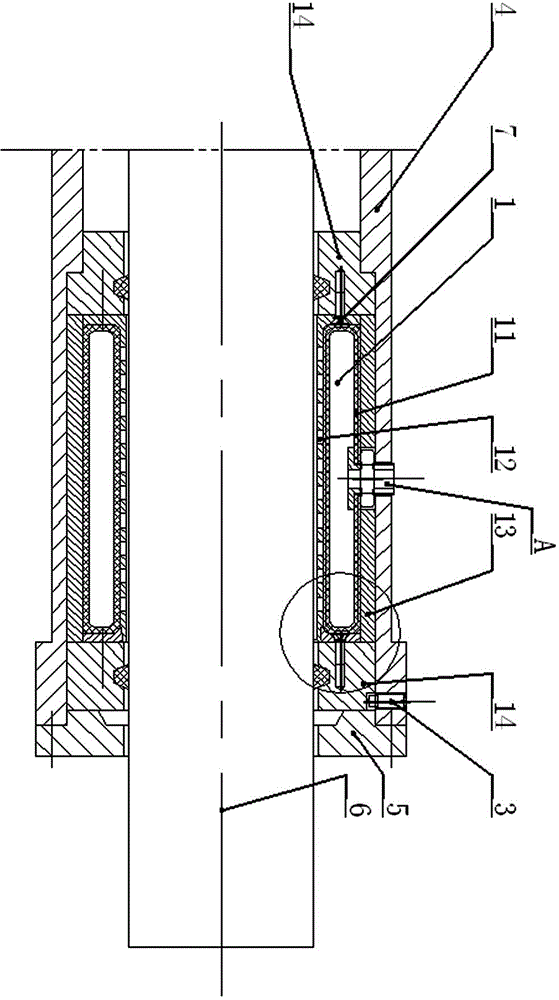
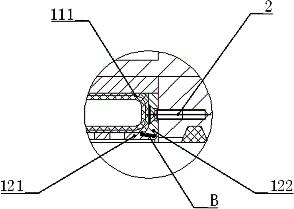
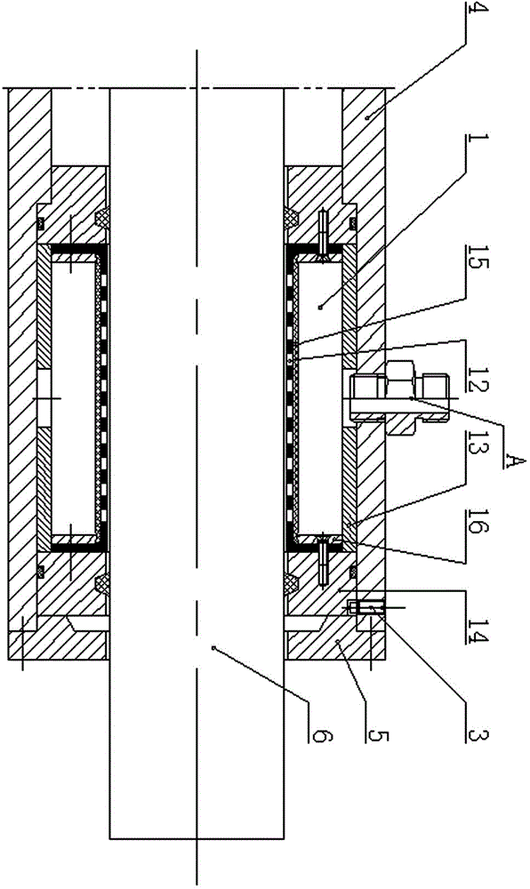
[0030] Such as figure 1 As shown, the present invention provides a kind of hydraulic locking mechanism, and this hydraulic locking mechanism comprises: Mechanism cylinder body 4, flange end cover 5, hydraulic cylinder piston rod 6, hydraulic oil bag 11, locking mesh cover 12, axial Support sleeve 13 and net cover support ring 14; Locking net cover 12 and net cover support ring 14 are sleeved on the piston rod 6, and there is a gap between the elastically deformable locking net cover 12 and the piston rod 6. Satisfied conditions are: when the locking net sleeve 12 undergoes elastic deformation, the locking net sleeve 12 can hold the piston rod 6 tightly; Lock the outer side of the net sleeve 12 and make contact with the net sleeve 12. The axial support sleeve 13 is installed on the outer side of the oil bag 11, and the outer side of the axial suppor...


PUM


Abstract

The invention provides a hydraulic locking mechanism, which comprises a mechanical cylinder body, a flange end cover, a hydraulic cylinder piston rod, a hydraulic oil sac, a locking net cover capable of elastic deformation, an axial support sleeve and net cover support rings, wherein the locking net cover and the net cover support ring are sleeved on the piston rod; a gap is remained between the locking net cover and the piston rod; the net cover support rings are arranged on two ends of the locking net cover through bolts; the hydraulic oil sac is sleeved on an outer side of the locking net cover and is contacted with the net cover; the axial support sleeve is arranged on an outer side of the oil sac; the mechanical cylinder body is arranged on an outer side of the axial support sleeve; and an oil inlet connected with the hydraulic oil sac is stretched to an outer end through a hole on the cylinder body. The hydraulic locking mechanism has the characteristics of easiness in manufacturing, convenient in maintenance, small volume, quick respond, high reliability and the like.

Description

technical field [0001] The invention relates to a locking mechanism for a self-locking hydraulic cylinder, in particular to a hydraulic locking mechanism which realizes locking by elastic deformation of elastic metal parts under the action of hydraulic pressure. Background technique [0002] In the hydraulic system, when the hydraulic cylinder is used as the actuator, sometimes it is necessary to keep the hydraulic cylinder at any position or a certain fixed point and bear a certain load force. At this time, the hydraulic cylinder needs to be locked. At present, hydraulic circuits are widely used to achieve For this purpose, but in special fields such as aircraft and submersibles, such as aircraft doors, compartments of submarines, etc., or when there is a high precision requirement for the actuator's working position, it is difficult for hydraulic circuit locking to meet reliability requirements. Contents of the invention [0003] Purpose of the invention: The present in...

Claims


Application Information

Patent Timeline
IPC IPC(8): F15B15/26
Inventor 闫明朱相军王世杰佟玲吕晓仁孙淑霞张明远
Owner SHENYANG POLYTECHNIC UNIV
Why Eureka
Try Eureka