
Lubricating-grease automatic filling device for bearing

An automatic filling and grease technology, applied in the direction of engine lubrication, engine components, mechanical equipment, etc., can solve the problems affecting natural gas export production tasks, uncertainty of the operating frequency of the guide wheel, deflection of the guide wheel, etc., to ensure Relative continuity and uniformity, ensuring proper lubrication, prolonging service life

Inactive Publication Date: 2013-03-20
CHINA PETROLEUM & CHEM CORP +1
View PDF8 Cites 0 Cited by
  • Summary
  • Abstract
  • Description
  • Claims
  • Application Information

AI Technical Summary

Problems solved by technology

The lubrication between the guide wheel and the fixed shaft is usually maintained by adding grease manually, so the uncertainty of human factors has a great influence on the lubrication effect, such as the uncertainty of the lubrication cycle and the action frequency of the guide wheel, manual Subjective differences in operation, as well as the influence of the environment and climate, and when the gas holder rises a lot, there is a certain degree of unsafety for workers to perform climbing operations
If the guide wheel bearing lacks lubricating grease and performs dry friction movement, the guide wheel will deflect under the gravity of the gas cabinet, and the shaft will be damaged in severe cases. The gas cabinet must be emptied of natural gas, and the shaft must be replaced after the gas cabinet is completely lowered. Cause production stagnation and affect natural gas export production tasks

Method used


Image

  • Lubricating-grease automatic filling device for bearing
  • Lubricating-grease automatic filling device for bearing

Examples


Embodiment Construction

[0017] In order to further disclose the technical solutions of the present invention, the following will be described in detail through examples in conjunction with the accompanying drawings:

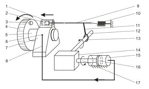
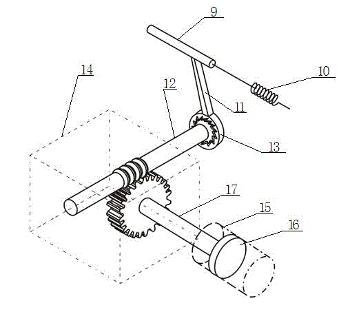
[0018] The present invention comprises a transmission mechanism, a deceleration mechanism and a grease filling mechanism, and is characterized in that the transmission mechanism comprises a guide wheel 4, a strong magnet 3 arranged on the inner surface of the guide wheel, and the end arranged on the guide wheel bearing frame 7 is opposite to the strong magnet The magnetic cylinder 1, the cylindrical magnetic core 2 located in the magnetic cylinder, the connecting rod 9 connected with the magnetic core, the coil spring 10 connected with the end of the connecting rod and fixed on the bracket, the belt swing rod connected with the outer circumference of the connecting rod The ratchet 13 of 11; The deceleration mechanism comprises reduction box 14, is provided with the input shaft 12 of line...


PUM


Abstract

The invention relates to a lubricating-grease automatic filling device for a bearing, comprising a transmission mechanism, a speed reducing mechanism and a lubricating-grease filling mechanism. The lubricating-grease automatic filling device is characterized in that the transmission mechanism comprises a guide wheel, a strong magnet, a magnetic cylinder, a cylindrical magnetic core, a connecting rod, a spiral spring and a ratchet wheel, wherein the strong magnet is arranged at the inside face of the guide wheel; the magnetic cylinder is arranged at the tail end on a bearing frame of the guide wheel and is opposite to the strong magnet; the cylindrical magnetic core is arranged in the magnetic cylinder; the connecting rod is connected with the magnetic core; the spiral spring is connected with the tail end of the connecting rod and is fixed on a bracket; the ratchet wheel is connected with the periphery of the connecting rod and is provided with a swinging rod; the speed reducing mechanism comprises a speed reducing box body, an input shaft and an output shaft; the input shaft is provided with a linear gear; the output shaft is provided with a variable-speed gear; the lubricating-grease filling mechanism comprises a cylindrical piston, an oil storage barrel and an oil filling pipe; the cylindrical piston is arranged at the end part of the output shaft; the oil storage barrel is sheathed at the periphery of the cylindrical piston and is fixed on the sliding bracket; the oil filling pipe is connected with oil filling nozzles on the oil storage barrel and the bearing frame; and the ratchet wheel is connected with the input shaft of the speed reducing box by a key, and the output shaft of the speed reducing box is in threaded connection with the oil storage barrel.

Description

technical field [0001] The invention relates to a transmission mechanism for filling lubricating grease of mechanical bearings, in particular to a device for automatically filling lubricating grease, which solves the problems of the bearings of the rotating guide rail of the spiral wet gas cabinet, the bearing of the fixed guide wheel and other mechanical bearings. Problems with automatic grease filling. Background technique [0002] During the normal operation of the spiral wet gas holder, the staff should often carry out normal maintenance on the spiral lifting mechanism. The lubrication between the guide wheel and the fixed shaft is usually maintained by adding grease manually, so the uncertainty of human factors has a great influence on the lubrication effect, such as the uncertainty of the lubrication cycle and the action frequency of the guide wheel, manual Subjective differences in operation, as well as the influence of the environment and climate, and when the g...

Claims


Application Information

Patent Timeline
Patent Type & Authority Applications(China)
IPC IPC(8): F16N11/08
Inventor 赵学俭赵勇李志兴沈健樊兆存杨青丁帅刘聪苏瑾
Owner CHINA PETROLEUM & CHEM CORP
Learn More