Machine vision LED (light emitting diode) illumination source

A technology of LED lighting and machine vision, applied in the field of machine vision LED lighting sources, can solve the problems of difficult control of reflected light of objects, non-adjustable light, unevenness, etc., and achieve rich brightness, incident angle, uniform light, and uniform lighting Effect

Inactive Publication Date: 2013-03-20
SOUTH CHINA UNIV OF TECH
View PDF5 Cites 16 Cited by
  • Summary
  • Abstract
  • Description
  • Claims
  • Application Information

AI Technical Summary

Problems solved by technology

At present, the fixed-angle forward lighting method is mainly used. The light source directly shines on the surface of the object, and can only light up all the LEDs at the same time (for LED light sources), resulting in non-adjustable angle and brightness and inconsistent light. Uniform, difficult to control the reflected light on the object

Method used


Image

  • Machine vision LED (light emitting diode) illumination source
  • Machine vision LED (light emitting diode) illumination source
  • Machine vision LED (light emitting diode) illumination source

Examples


Embodiment

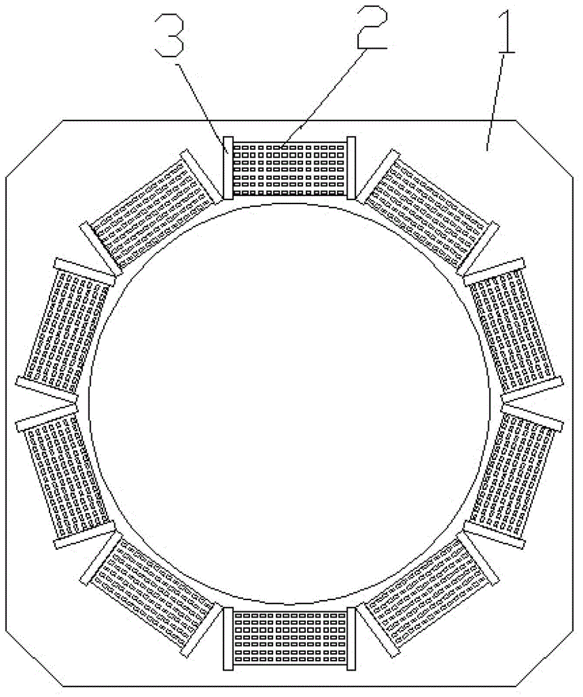
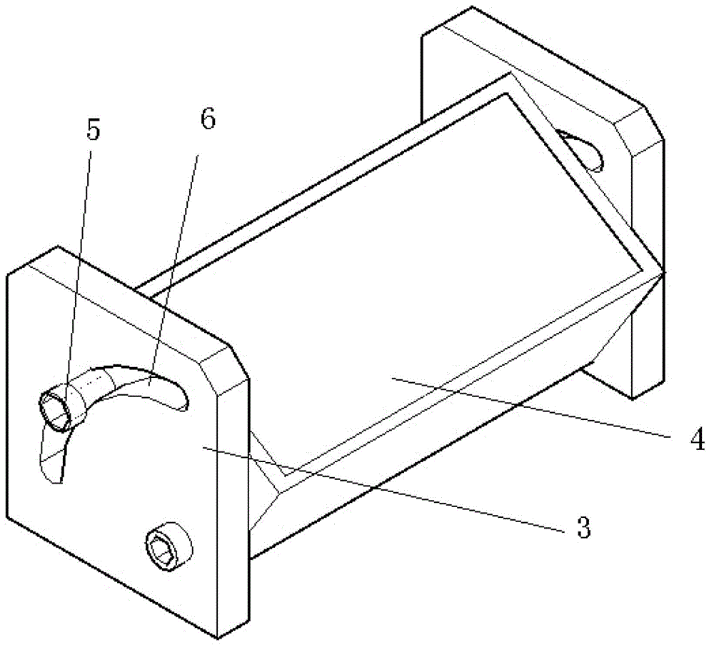
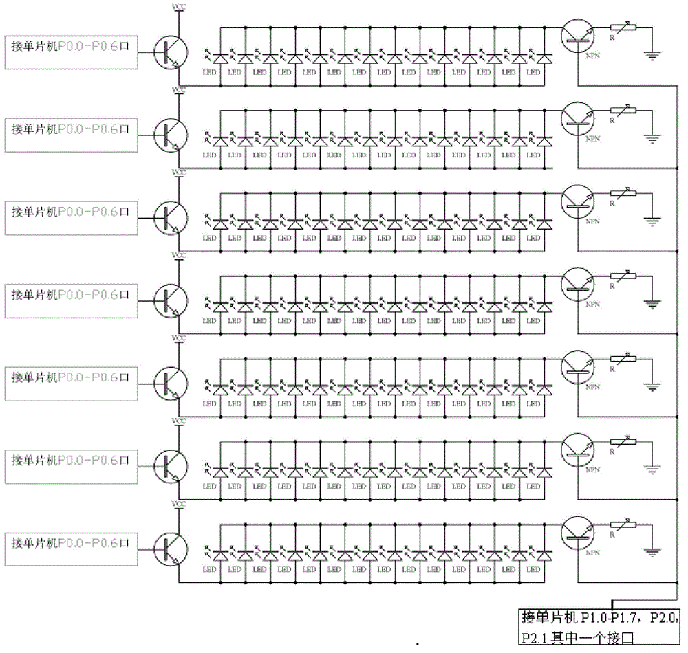
[0018] Such as figure 1 , 2 As shown, the machine vision LED lighting source of the present invention includes a bottom controller (not shown in the figure), a seat 1, and a matrix light source assembly installed on the base 1. The matrix light source assembly includes two brackets 3 and is movably installed on LED matrix light source 2 between two brackets 3 . Arc-shaped chute 6 is respectively arranged on two brackets 3, and slide bar 5 is set on both sides of LED matrix light source 2 corresponding to the position of arc-shaped chute 6, and slide bar 5 is placed in arc-shaped chute 6, and slide bar 5 Slidingly connected with arc chute 6. The number of said matrix light source components is 10, and they are installed on the base 1 in an equidecagonal shape. The controller is connected with the LED matrix light source 2 .

[0019] Arc-shaped chute 6 is respectively arranged on two brackets 3, and slide bar 5 is set on both sides of LED matrix light source 2 corresponding ...


PUM


Abstract

The invention discloses a machine vision LED (light emitting diode) illumination source, which comprises a base and ten matrix light source assemblies arranged on the base, wherein each matrix light source assembly comprises two support frames and a LED matrix light source movably arranged between the two support frames, the matrix light source assemblies are arranged on the base in the equilateral decagonal shape, the LED matrix light sources are connected with a controller, diffusing panels are arranged at the irradiation surfaces of the LED matrix light sources, and light rays become uniform through the diffusing effect of the diffusing panels. Compared with the existing annular light source, the machine vision LED illumination source has the advantages that richer brightness and incident angles can be obtained under the condition of not moving a lampshade, and in addition, the light rays are uniform. The machine vision LED illumination source can adapt to more application occasions, the uniform illumination on tested objects in different sizes can also be realized, and the target feature is obvious as far as possible.

Description

technical field [0001] The invention relates to the field of photoelectric lighting, in particular to a machine vision LED lighting source. Background technique [0002] Machine vision is to use machines instead of human eyes for measurement and judgment. Through machine vision products (that is, image capture devices, which are divided into CMOS and CCD), the captured objects are converted into image signals and sent to a dedicated image processing system. According to the pixel Distribution, brightness, color and other information are converted into digital signals; the image system performs various operations on these signals to extract the characteristics of the target, and then controls the on-site equipment actions according to the results of the discrimination. The feature of machine vision is to improve the flexibility and automation of production. In some dangerous working environments that are not suitable for manual work or where artificial vision is difficult to...

Claims


Application Information

Patent Timeline
Patent Type & Authority Applications(China)
IPC IPC(8): F21S8/00F21V21/116F21V5/08F21Y101/02F21Y115/10
Inventor 欧阳高飞孙海杰林俊强李涛李锋涛
Owner SOUTH CHINA UNIV OF TECH
Why Eureka
Try Eureka