Ultrasonic impact needle speed measurement experiment equipment and application thereof

A technology of ultrasonic impact and experimental equipment, which is applied in the field of ultrasonic impact, and can solve the problems of small distance between the impact needle and the test piece, complex changes in the velocity of the impact needle, etc.

Active Publication Date: 2013-03-20
天津益普科技发展有限公司
View PDF5 Cites 3 Cited by
  • Summary
  • Abstract
  • Description
  • Claims
  • Application Information

AI Technical Summary

Problems solved by technology

[0005] The present invention aims at the deficiencies of the prior art, in order to solve the problem that the speed of the impact needle changes complicatedly during the ultrasonic impact process,

Method used


Image

  • Ultrasonic impact needle speed measurement experiment equipment and application thereof
  • Ultrasonic impact needle speed measurement experiment equipment and application thereof
  • Ultrasonic impact needle speed measurement experiment equipment and application thereof

Examples


Embodiment 1

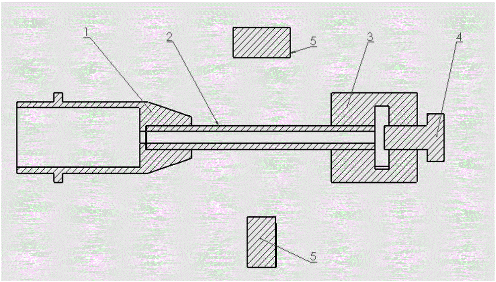
[0024] Embodiment 1: Assembling an infrared velocimeter

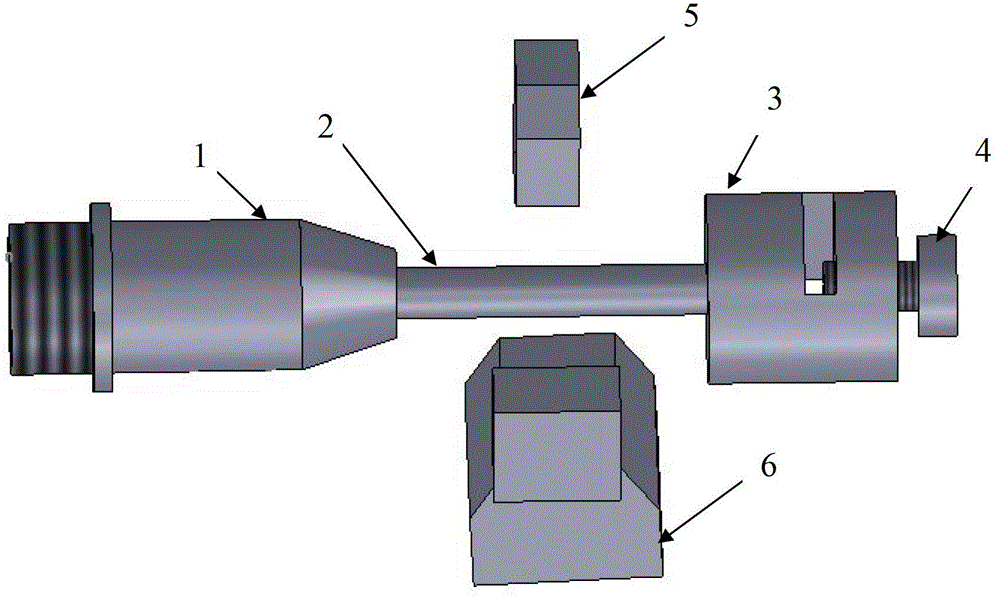
[0025] as attached Figure 1-2 As shown, in the experimental process of the present invention, an infrared velocimeter can be used to collect the velocity of the impacting needle during the impact process, and its structure includes: a base 1, a quartz tube 2, a sample holder 3, a fixing screw 4 and an infrared velocimeter 5.

[0026] The end of the cylindrical base is threaded to match the ultrasonic impact gun body, and it also has a loading and unloading protrusion, which can be used to fix the base and the gun body with a flange. connect. The role of the quartz tube is to extend the stroke of the impact needle, which is beneficial to the observation and collection of the speed change of the impact needle during the impact process, and to connect the base and the sample holder. The sample is clamped into a cylindrical shape, and one end has a hole with the same diameter as the outer diameter of the quartz tube, the...

Embodiment 2

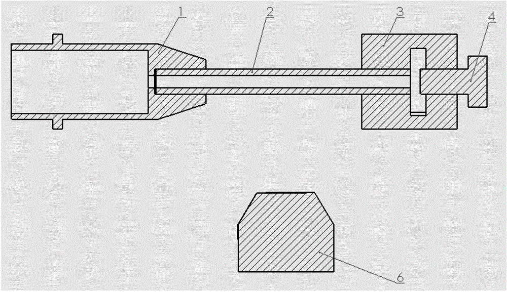
[0027] Example 2: Assembling a high-speed camera

[0028] as attached Figure 1-3 As shown, in the experimental process of the present invention, an infrared velocimeter can be used to collect the impact needle velocity during the impact process, and its structure includes: a base 1, a quartz tube 2, a sample holder 3, a fixing screw 4 and a high-speed camera 6.

[0029] The end of the cylindrical base is threaded to match the ultrasonic impact gun body, and it also has a loading and unloading protrusion, which can be used to fix the base and the gun body with a flange. connect. The role of the quartz tube is to extend the stroke of the impact needle, which is beneficial to the observation and collection of the speed change of the impact needle during the impact process, and to connect the base and the sample holder. The sample is clamped into a cylindrical shape, and one end has a hole with the same diameter as the outer diameter of the quartz tube, the other end has a thre...


PUM


Abstract

The invention discloses ultrasonic impact speed measurement experiment equipment and an application of the ultrasonic impact speed measurement experiment equipment. The ultrasonic impact speed measurement experiment equipment and the application of the ultrasonic impact speed measurement experiment equipment comprises a base seat, a quartz tube, a sample clamp, a fixing screw, an infrared speed measuring instrument and a high speed camera, wherein the base seat, the quartz tube, the sample clamp, the fixing screw are used for fixing a sample and the ultrasonic impact gun, and the infrared speed measuring instrument and the high speed camera are used for measuring speed and a camera. The ultrasonic impact speed measurement experiment equipment and the application of the ultrasonic impact speed measurement experiment equipment is mainly used for measuring changing of the speed of an impact pin and observing detailed motion situations of the impact pin during an impacting process, and can have a more intuitive understanding of the impact process, and therefore the principle of the ultrasonic impacting can be analyzed more profoundly and a function of optimizing ultrasonic impact process parameters are achieved.

Description

technical field [0001] The invention belongs to the technical field of ultrasonic impact, and more specifically relates to a novel ultrasonic impact needle velocity measurement experimental equipment. Background technique [0002] Due to uneven temperature changes during the welding process, welding residual stress will be generated after welding. Especially the joint part is the weak link in the whole structure. There are often various welding defects, stress concentration and tensile welding residual stress at the weld toe of the welded joint. These reasons cause the fatigue strength of the welded joint to be much lower than that of the mother The level of the material metal. The influence of residual stress on structural fatigue strength is a problem that people are very concerned about, and a lot of manpower and material resources have been invested in research. The research results show that the influence of welding residual stress on fatigue strength is related to th...

Claims


Application Information

Patent Timeline
IPC IPC(8): G01P3/36G01P3/38
Inventor 邓彩艳黄超王东坡吴良晨龚宝明
Owner 天津益普科技发展有限公司
Why Eureka
Try Eureka