
Shield circuit used for improving ground field strength of direct current transmission line

A technology of DC transmission lines and shielded wires, which is applied in the installation of cables, spatial arrangement/configuration of cables, electrical components, etc., can solve the problems of lack of research on ion currents, radio interference of shielded wires, etc., and achieve optimized design schemes and economical construction Cost, the effect of reducing demolition cost

Inactive Publication Date: 2013-03-20
ELECTRIC POWER RESEARCH INSTITUTE, CHINA SOUTHERN POWER GRID CO LTD +1
View PDF2 Cites 5 Cited by
  • Summary
  • Abstract
  • Description
  • Claims
  • Application Information

AI Technical Summary

Problems solved by technology

However, the effect of shielded wires on radio interference, audible noise, and ion currents is still lacking in research

Method used


Image

  • Shield circuit used for improving ground field strength of direct current transmission line
  • Shield circuit used for improving ground field strength of direct current transmission line

Examples


Embodiment 1

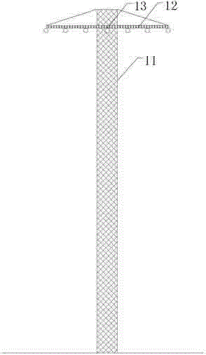
[0028] This embodiment adopts the above-mentioned shielded circuit structure, such as figure 1 As shown; the voltage applied to the pole wire is ±800kV, the total length of the shielded wire is 300m, and the center span is 400m.

[0029] The shielded wire tower body of this embodiment adopts cement pole 11; the shielded wire adopted is a single shielded wire of LGJ-70 / 40 type (not shown in the figure), and is suspended on the central hanging point 13 of the cross arm 12 (Fig. The 7 circles on the middle crossarm are the hanging points); this setting produces the best suppression effect on the synthetic field strength on the ground. The shielded wire tower is erected on the side of the positive polarity wire. The height of the tower is 20m, and the nominal height is 19m; the height of the suspension point is 19m, the sag is 7m, the minimum height to the ground is 12m, and the average height is 15.33m. The shielding wire is directly connected to the tower at the hanging point o...

Embodiment 2

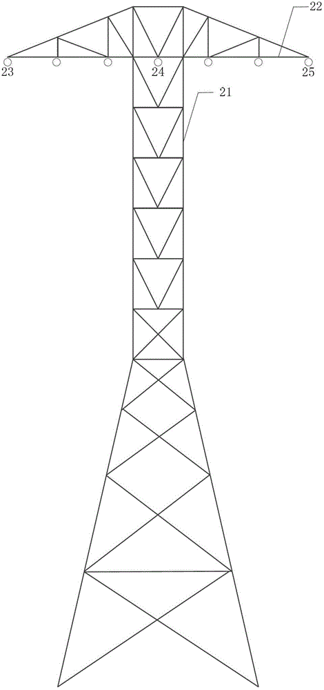
[0031] The applied voltage of the pole wire, the total length of the shielding wire, and the center span are 400m with the embodiment 1. The shielded line pole tower body of the present embodiment adopts steel pole tower 21, as figure 2 As shown; the shielded wires used are 3 shielded wires of the LGJ-300 / 70 model, and the three shielded wires are suspended on the head end hanging point 23, the middle hanging point 24 and the end hanging point 25 of the cross arm 22 (the cross arm in the figure The 7 circles above are the hanging points), and this setting produces the best suppression effect on the ground synthetic field strength. The shielded wire tower is erected on the side of the negative wire, the tower is 17m high, and the name is 16m high. Taking the negative wire as a reference, the relative horizontal positions of the three shielded wires are the center of the negative wire, 3m outside, and 6m outside. The height of the suspension point is 16m, the sag is 7m, the m...


PUM


Abstract

The invention discloses a shield circuit used for improving ground field strength of a direct current transmission line and belongs to the technical field of transmission line electromagnetic environment protection in electric systems. The shield circuit comprises a plurality of shield wires, a shield wire tower body used for supporting the shield wires and a layer of a cross arm matched with the shield wire tower body, and a plurality of suspension points used for suspending shield wire suspension parts are arranged on the cross beam and a tow top; and a plurality of shield wire suspension points are arranged on the cross beam at equal intervals to suspend shield wires of different arrangement mode. A center shaft of a shield wire tower relative to a horizontal position is 3m outside of a straight line where a center of a transmission wire is in. According to the shield circuit, electromagnetic environment parameters around the direct current transmission line are controlled on the premise of not changing a construction scheme of original power transmission lines. Ground synthetic field strength is controlled on the premise of not improving radio interference, audible noise and corona loss, the construction cost can be greatly saved, and simultaneously, power transmission corridors are reduced, so that ultra high voltage direct current transmission projects are economical and reasonable.

Description

technical field [0001] The invention belongs to the technical field of electromagnetic environment protection for power system transmission lines, and relates to a shielding line for improving the ground field strength of direct current transmission lines. Background technique [0002] The corona phenomenon of high-voltage transmission lines is a key technical issue that needs to be considered in engineering design, construction and operation. On the one hand, corona will cause power loss and increase the cost of power transmission. On the other hand, the radio interference, audible noise and space ion flow generated by corona will affect the electromagnetic environment around the transmission line. With the continuous development of the economy and the enhancement of people's environmental awareness, electromagnetic environmental problems have attracted more and more attention, especially in UHV DC projects, due to the increase in voltage levels, electromagnetic environment...

Claims


Application Information

Patent Timeline
Patent Type & Authority Applications(China)
IPC IPC(8): H02G7/00H02G7/20
Inventor 余占清刘磊曾嵘田丰戴梦婷李锐海李敏张波尹晗
Owner ELECTRIC POWER RESEARCH INSTITUTE, CHINA SOUTHERN POWER GRID CO LTD
Learn More