Supercharge Your Innovation With Domain-Expert AI Agents!

VGA video signal pattern recognition method

A VGA mode, pattern recognition technology, applied in the direction of television, image communication, electrical components, etc., can solve the problems of inaccurate recognition, pattern recognition video signal acquisition and processing errors, sampling data errors, etc., to achieve a simple identification method, improve display effect, the effect of improving the accuracy

Active Publication Date: 2015-06-17
ATEL TECH CO LTD
View PDF7 Cites 0 Cited by
  • Summary
  • Abstract
  • Description
  • Claims
  • Application Information

AI Technical Summary

Problems solved by technology

But, adopt this kind of method in the prior art, there will be these defects in application: because only 3 signal parameters can be obtained directly through hardware measurement in the 4 signal parameters of VGA video signal, so may not recognize part VGA video mode Accurate, it is recognized as a VGA video mode similar to it, which will lead to sampling data errors, and finally lead to unsatisfactory display effects
The reason for this kind of error is that there are some approximate modes in the standard VGA video mode. The so-called approximate mode means that their HPer, VPer and VTotal are very close, but there is a big difference in HTotal, and the output timing of different graphics cards will be slightly different. These three signal parameters obtained directly by hardware measurement may be recognized as similar modes when looking up in the standard VGA mode table
In many approximate modes, their timing parameters are very different, such as 1280*76860Hz and 1366*76860Hz. The HPer, VPer, and VTotal of these two modes are very close, but the front shoulder HFrontPorch and the back shoulder HBackPorch in the horizontal direction , the synchronization width HSyncWidth, the front shoulder VFrontPorch, the back shoulder VBackPorch, and the synchronization width VSyncWidth in the vertical direction have a large difference, so the conventional method cannot identify the VGA video signal mode very accurately, and the wrong mode recognition will lead to the collection and processing of the video signal. Handle an error

Method used


Image

  • VGA video signal pattern recognition method

Examples


Embodiment Construction

[0013] In order to enable those skilled in the art to better understand the solutions of the embodiments of the present invention, the specific embodiments of the present invention will be further described in detail below in conjunction with the accompanying drawings.

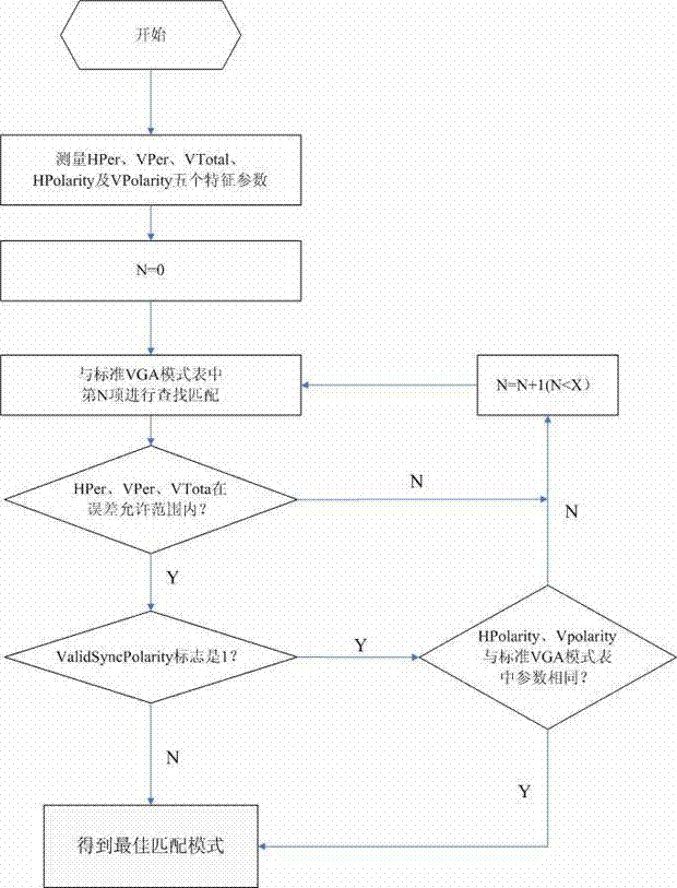
[0014] The necessary parameters in the general standard VGA mode table are: line frequency HPer, horizontal front porch HFrontPorch, horizontal sync width HSyncWidth, horizontal back porch HBackPorch, horizontal effective pixel number HActivePixel, field frequency VPer, vertical front porch VFrontPorch, Signal parameters such as the vertical sync width VSyncWidth, the vertical back porch VBackPorch, and the effective number of lines of data per field VActiveLine. This method adds 3 new signal parameters in the standard VGA mode table: horizontal synchronization polarity HPolarity, vertical synchronization polarity VPolarity and polarity valid flag ValidSyncPolarity (this flag is represented by 1 and 0, 1 repres...


PUM


Abstract

The invention discloses a VGA (Video Graphics Array) video signal pattern recognition method. The method comprises the following steps: measuring the horizontal synchronizing signal and the vertical synchronizing signal of a VGA signal through hardware to obtain five signal parameters, namely HPer, VPer, VTotal, HPolarity and VPolarity; meanwhile, adding three parameters, namely HPolarity (Horizontal synchronous polarity), VPolarity (Vertical synchronous polarity) and ValidSyncPolarity (Polarity valid flag) in a standard VGA pattern list; and carrying out finding and matching on the obtained five signal parameters, namely HPer, VPer, VTotal, HPolarity and VPolarity and the parameters in the standard pattern list, so as to obtain an accurate video signal pattern. According to the invention, a traditional VGA video signal pattern recognition method is improved, so that the accuracy rate of VGA video signal pattern recognition is increased, and the display effect is improved after the VGA video signal is digitally processed.

Description

technical field [0001] The invention relates to the technical field of acquisition of analog video signals and digital processing of analog video signals, in particular to a VGA video signal pattern recognition method. . Background technique [0002] When digitizing the VGA video signal, an accurate identification mode is required, and the mode of a VGA video signal can be determined by the line frequency (HPer), the field frequency (VPer), the total number of lines of each image (VTotal), and the data of each line. The four signal parameters of the total number of pixels (HTotal) are uniquely determined, that is, when these four parameters are determined, the mode of the VGA video signal is determined. [0003] In the prior art, it is mainly to directly measure the HPer, VPer and VTotal three signal parameters of the VGA video signal by hardware, and use these three parameters to find the VGA video signal mode consistent with its parameters or the closest in a standard mod...

Claims


Application Information

Patent Timeline
Patent Type & Authority Patents(China)
IPC IPC(8): H04N17/00
Inventor 不公告发明人
Owner ATEL TECH CO LTD
Features
  • R&D
  • Intellectual Property
  • Life Sciences
  • Materials
  • Tech Scout
  • Unparalleled Data Quality
  • Higher Quality Content
  • 60% Fewer Hallucinations
Learn More