
Decoding device and coding device

A technology of decoding device and encoding device, which is applied in the direction of TV, pulse modulation TV signal transmission, electrical components, etc., can solve the problem that the prediction mode cannot be used, and achieve the effect of improving accuracy

Active Publication Date: 2013-03-20
SHARP KK
View PDF5 Cites 6 Cited by
  • Summary
  • Abstract
  • Description
  • Claims
  • Application Information

AI Technical Summary

Problems solved by technology

[0038] Therefore, in Figure 24 When the shown prediction set PS400 is a prediction set of adjacent blocks, the prediction mode whose prediction direction is F1 (the prediction mode of the prediction mode IMP401 of the prediction set PS400 ) cannot be used when estimating the prediction mode. question
[0039] That is, in the technology of Non-Patent Document 2, there is a problem that the prediction mode derived as the estimated prediction mode is not limited to the above-mentioned representative prediction mode.

Method used


Image

  • Decoding device and coding device
  • Decoding device and coding device
  • Decoding device and coding device

Examples


Embodiment Construction

[0083] Below, refer to Figure 1 to Figure 21 One embodiment of the present invention will be described.

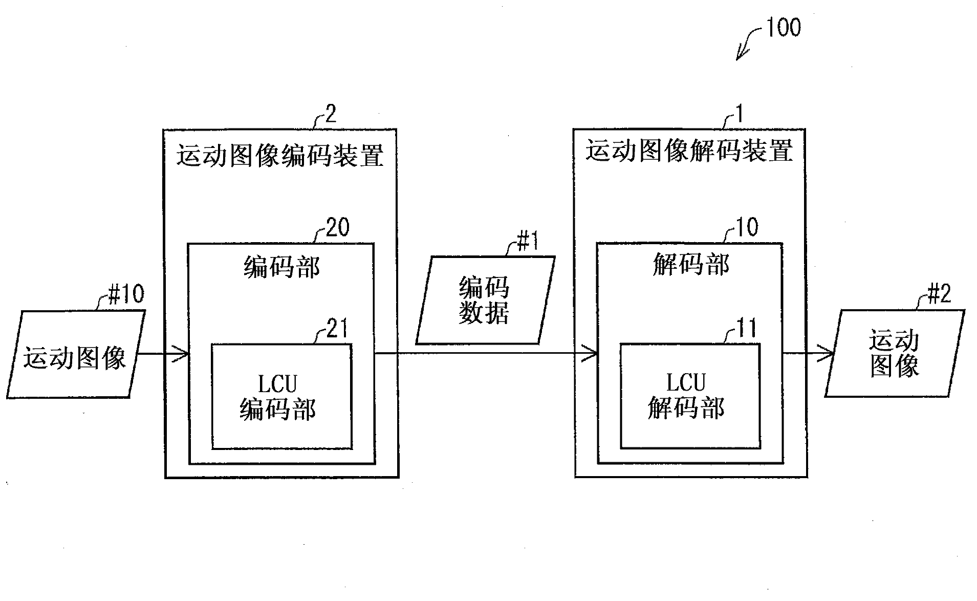
[0084] First, use figure 2 Next, the outline of the video encoding device (encoding device) 2 and the video decoding device (decoding device) 1 according to the present embodiment will be described. figure 2 It is a block diagram showing a schematic configuration of a video coding system 100 composed of a video coding device 2 and a video decoding device 1 .

[0085] figure 2 The moving picture coding device 2 and the moving picture decoding device 1 shown include technologies employed in H.264 / MPEG-4.AVC and KTA software, respectively.

[0086] The moving picture coding device 2 receives the moving picture #10 as an input, and the moving picture coding device 2 generates coded data #1 by coding the moving picture #10 in the coding unit 20 . The video encoding device 2 supplies the generated encoded data #1 to the video decoding device 1 .

[0087] The video decod...


PUM


Abstract

Provided is a moving image decoding device (1) which is structured so as to be equipped with an interim estimated prediction mode derivation unit (124) for transforming a prediction mode for each adjacent partition to an interim prediction mode contained in an interim prediction set which is a union of prediction sets (PS), and an estimated prediction mode derivation unit (125) for deriving an estimated prediction mode by estimating a prediction mode for each partition to be processed on the basis of the interim prediction mode for each adjacent partition obtained by the transformation.

Description

technical field [0001] The present invention relates to an encoding device for encoding images and a decoding device for decoding encoded images. Background technique [0002] In order to efficiently transmit or record moving images, a moving image encoding device that generates encoded data by encoding a moving image, and a moving image decoding device that generates a decoded image by decoding the encoded data are used. As a specific video encoding method, for example, H.264 / MPEG-4.AVC (Non-Patent Document 1) and VCEG (Video Coding Expert Group; Video Coding Expert Group) jointly developed encoder, that is, KTA Software The method used, etc. [0003] In such an encoding method, an image (picture) constituting a moving image consists of slices obtained by dividing the image, macroblocks obtained by dividing the slice, and macroblocks obtained by dividing the macroblock. The resulting block (block) is managed in a hierarchical structure and coded for each block. [0004] ...

Claims


Application Information

Patent Timeline
IPC IPC(8): H04N7/32
CPCH04N19/00375H04N7/26074H04N7/26026H04N19/00763H04N19/00884H04N19/00533H04N19/00042H04N7/26335H04N7/32H04N19/00551H04N19/00569H04N7/26946H04N19/00369H04N19/11H04N19/197H04N19/44H04N19/463H04N19/593H04N19/70H04N19/196
Inventor 山本智幸猪饲知宏
Owner SHARP KK
Learn More