
Electroless welding type welding rod and preparation and welding method thereof

A welding rod and bonding technology, applied in the field of electroless welding electrode and its preparation and welding, can solve the problems of long bonding and curing time, large engineering, limited application, etc., to solve emergency welding maintenance, simple and rapid operation , The effect of improving welding quality

Inactive Publication Date: 2013-03-27
ARCHITECTURAL ENG INST GENERAL LOGISTICS DEPT P L A
View PDF8 Cites 31 Cited by
  • Summary
  • Abstract
  • Description
  • Claims
  • Application Information

AI Technical Summary

Problems solved by technology

Welding is one of the important technical means for emergency maintenance of equipment. At present, the commonly used welding techniques are arc welding and gas welding. However, the special geographical environment and harsh working conditions of the emergency maintenance site make it difficult to guarantee high-power power supply and gas storage equipment.
[0004] Under normal circumstances, when construction machinery or military weaponry is used in the field, there are often inevitable damages and pipeline breaks to parts such as engines and transmissions, such as box cracks, cracks, pores, and oil and water pipelines, tanks, etc. Running, popping, dripping, leaking and other phenomena of the body will seriously affect the normal use and training of construction machinery
Traditional field emergency maintenance methods, such as electric welding, gas welding, and gluing, require professionals and special equipment such as vehicles, electricity, gas, and tools for repairs. The involved projects are relatively large, and the bonding and curing time is long, which cannot meet the emergency use in the field. need
[0005] In addition, under the conditions of inconvenient supply of energy such as high altitude, underground, and underwater, these traditional emergency maintenance methods cannot be used
At the same time, in today's increasingly tense energy environment, traditional welding technology has limited its application due to the need to use a large amount of energy during welding.

Method used


Image

  • Electroless welding type welding rod and preparation and welding method thereof
  • Electroless welding type welding rod and preparation and welding method thereof

Examples


Embodiment Construction

[0018] The present invention is described in further detail below in conjunction with accompanying drawing:

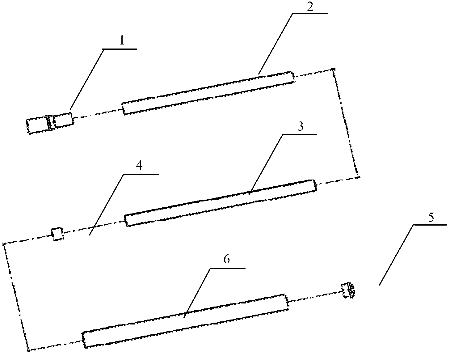
[0019] see figure 1 and figure 2 , the electroless welding electrode of the present invention comprises a plug 1, a powder column 2, a paper tube 3, a fire cap 4, a tube plug 5 and a sleeve 6; the plug 1 and the paper tube 3 are coaxially bonded by latex Together, the powder column 2 and the fire starter 4 are formed in the paper tube 3, the sleeve 6 is set on the paper tube 3, one end of the sleeve 6 is tightly connected with the plug 1, and the other end is sealed by the tube plug 5 . The main system of grain 2 is CuO+Al, Fe 2 o 3 +Al, SiO 2 , CaO, TiO 2 and silicates. In terms of mass percentage, the composition ratio of the powder column is: CuO+Al: 40.03-40.60%; Fe 2 o 3 +Al: 30.05~30.90%; CaO: 12.4~13.40%; SiO 2 : 6.2~7.50%; CaF 2 : 0.5~0.90%; TiO 2 Ni: 4.3~5.6%; Ni: 1.02~1.40%; Mn: 2~3%; Ti: 2~3.4%.

[0020] The present invention proposes a method ...


PUM


Abstract

The invention discloses an electroless welding type welding rod and a preparation and welding method thereof. The electroless welding type welding rod comprises a plug, a grain, a paper pipe, an igniting cap, a pipe plug and a sleeve pipe, wherein the plug and the paper pipe are coaxially adhered together through emulsions; the grain and the igniting cap are formed in the paper pipe; the sleeve pipe is sleeved on the paper pipe; one end of the sleeve pipe is connected with the plug in a close fit way, and the other end of the sleeve pipe is sealed through the pipe plug. According to the electroless welding type welding rod, a welding material is manufactured into a special hand-held pencil, the special hand-held pencil can initiate reaction by being only ignited through matches, a reaction product and a parent material are molten by taking the self-releasing chemical energy of a thermite as a welding heat source, and the firm connection of the welded parent material is realized through mechanisms such as wetting, diffusion and reaction crystallization.

Description

technical field [0001] The invention belongs to the technical field of welding materials, and relates to a welding rod, in particular to a non-electric welding welding rod and a preparation and welding method thereof. Background technique [0002] Welding technology is not only widely used in industrial production, but also one of the important means of emergency repair of battlefield equipment and civil machinery. When the parts of mechanical equipment are broken, cracked, perforated, damaged, etc. during use, most of them must be used. Repaired by welding. At present, manual arc welding or gas welding is generally used in mechanical emergency repairs. Arc welding requires a power supply with an output power of more than one kilowatt and an electric welding machine weighing more than tens of kilograms. Gas welding requires high-voltage equipment that stores oxygen and acetylene gas. The operator needs to pass through Strict specialized training greatly limits the mobility,...

Claims


Application Information

Patent Timeline
Patent Type & Authority Applications(China)
IPC IPC(8): B23K35/14B23K35/368B23K35/40B23K23/00
Inventor 王胜军高勇李宝峰侯忠明田新民姚凯辛涛赵晓文侯宝科
Owner ARCHITECTURAL ENG INST GENERAL LOGISTICS DEPT P L A
Learn More