Constant tension diaphragm discharging device

A technology of unwinding device and constant tension, which is applied in the direction of thin material handling, transportation and packaging, and winding strips, etc. It can solve the problems of difficulty in ensuring accuracy, inability to increase lamination speed, and low production efficiency, so as to improve quality and Accuracy, diaphragm tension stability, and the effect of saving manufacturing costs

Active Publication Date: 2013-03-27
DONGGUAN ARECONN PRECISION MACHINERY
View PDF11 Cites 28 Cited by
  • Summary
  • Abstract
  • Description
  • Claims
  • Application Information

AI Technical Summary

Problems solved by technology

[0004] 1. Due to the constant change of the tension of the diaphragm, the produced cells are constantly pulled by the changing force, and the accuracy is difficult to guarantee
[0005] 2. The production efficiency is very low. Due to the influence of the changing force on the properties of the diaphragm, the speed of the lamination cannot be increased.

Method used


Image

  • Constant tension diaphragm discharging device
  • Constant tension diaphragm discharging device
  • Constant tension diaphragm discharging device

Examples


Embodiment Construction

[0030] In order to further illustrate the principle and structure of the present invention, preferred embodiments of the present invention will now be described in detail with reference to the accompanying drawings.

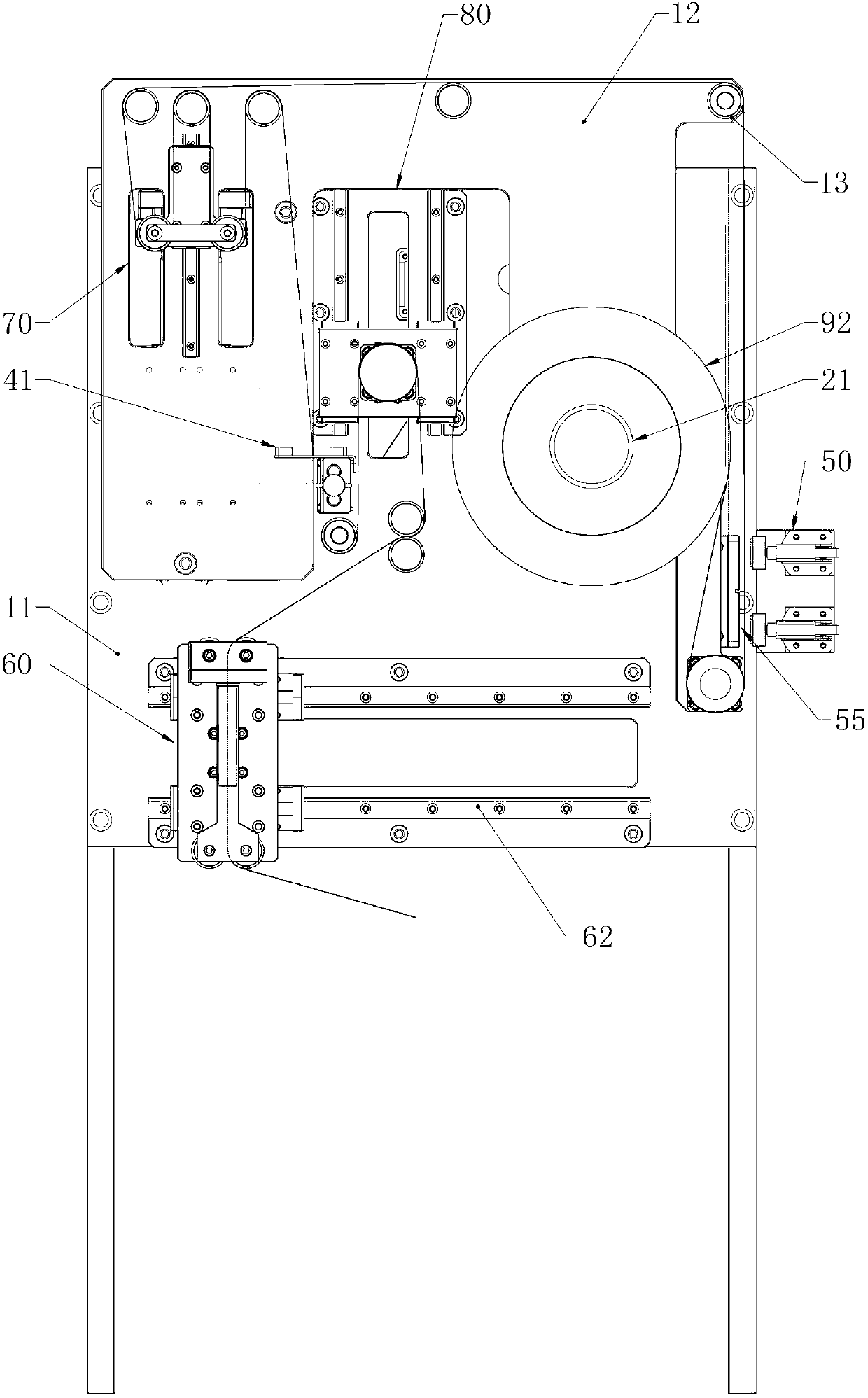
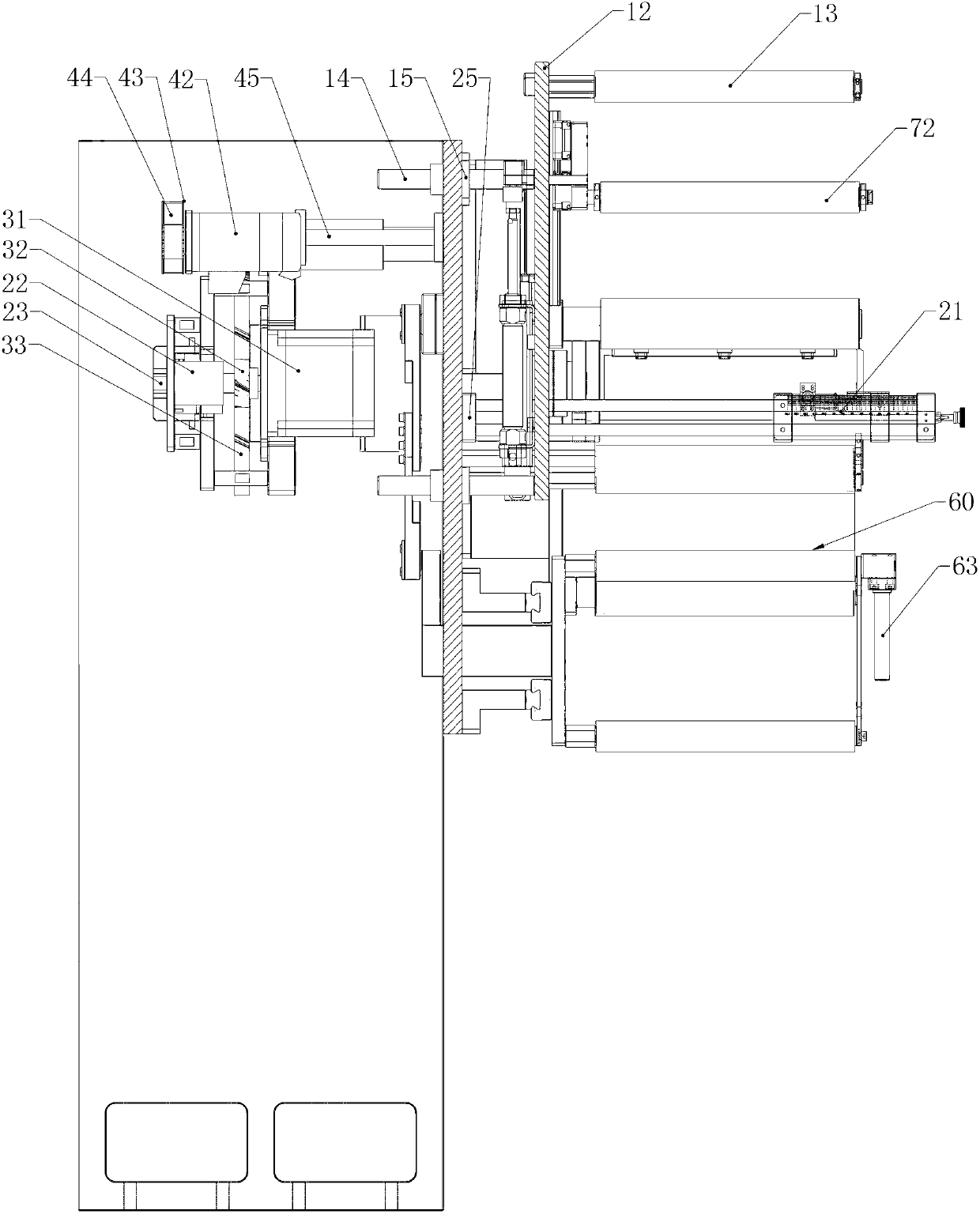
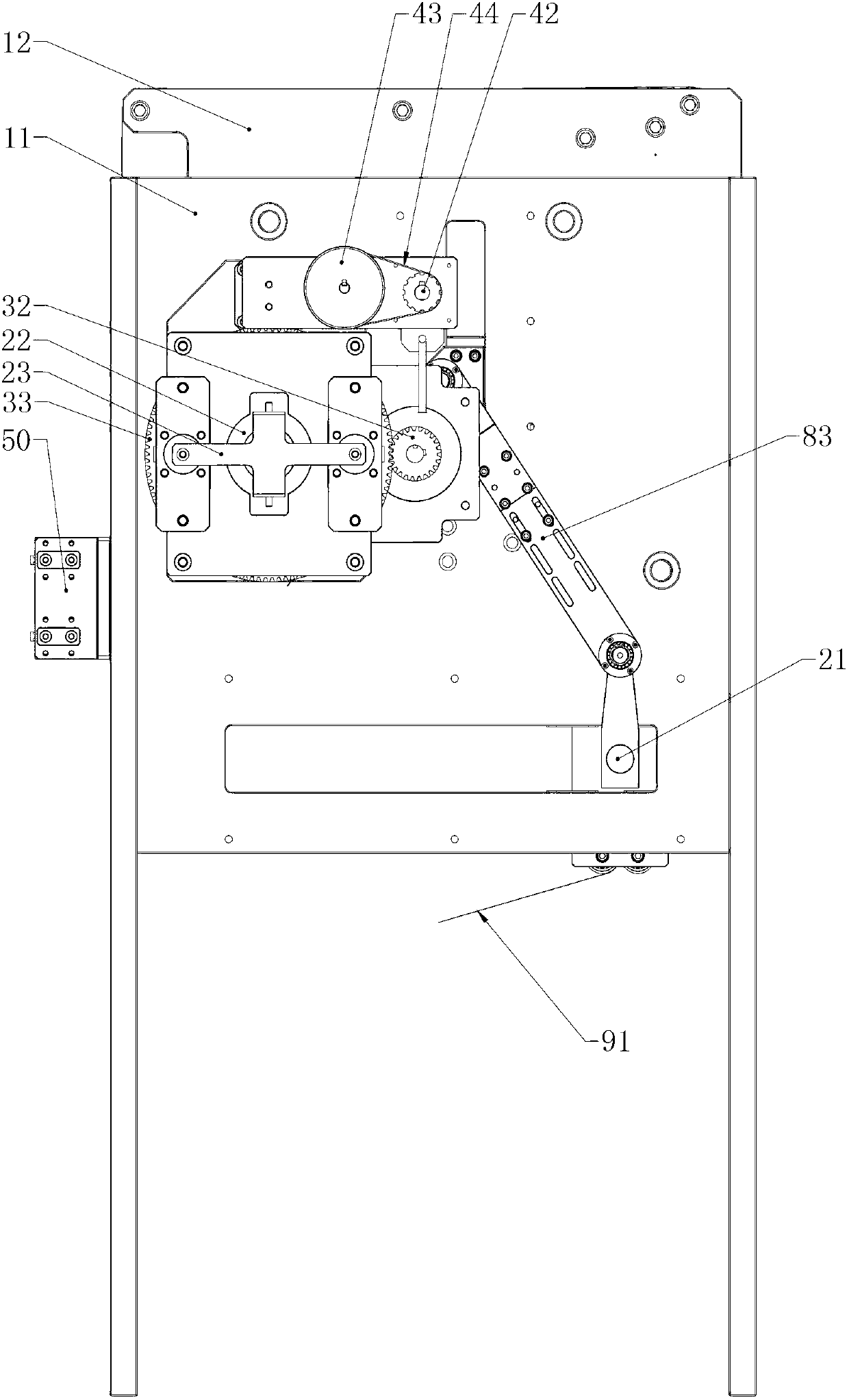
[0031] figure 1 It is the front view of the embodiment of the diaphragm discharging device with the expansion cylinder of the present invention, figure 2 is the left side view of the embodiment, image 3 is the rear view of this embodiment.

[0032] The embodiment of the constant tension diaphragm unwinding device of the present invention includes an unwinding mechanism 20 for installing the diaphragm material roll 92, a transmission mechanism 30 for driving the unwinding mechanism 20 to rotate, a deviation correction mechanism 40 for controlling the running accuracy of the diaphragm 91, and a device for connecting the diaphragms. Belt connection mechanism 50; and reciprocating diaphragm stacking mechanism 60 for diaphragm folding and discharging, providing te...


PUM


Abstract

The invention provides a constant tension diaphragm discharging device for a lamination stacking machine. The discharging device comprises an unreeling mechanism which is installed with a reeled diaphragm, a diaphragm laminating mechanism for folding and putting a diaphragm, a collecting and discharging connecting rod mechanism which is linked with the diaphragm laminating mechanism and keeps the diaphragm buffer length and a tension control mechanism which provides the diaphragm discharging tension. The tension control mechanism comprises a diaphragm fixing roll for guiding the diaphragm, a diaphragm floating roll for regulating the diaphragm buffer length, a sliding guide rail for installing the floating roll, a tension controller which pushes the floating roll to slide so as to change the buffer length and a position sensor for detecting the position information of the floating roll. The diaphragm laminating mechanism comprises a sliding roller group which drives the diaphragm to be discharged and a horizontal sliding rail for installing the sliding roller group. The collecting and discharging connecting rod mechanism comprises a collecting and discharging roller which is controlled by the diaphragm laminating mechanism, a vertical sliding rail for installing the collecting and discharging roller and a collecting and discharging connecting rod which connects the collecting and discharging roller with the sliding roller group. The discharging device has the advantages that the collecting and discharging connecting rod is matched with the tension control mechanism, so that the constant tension control of the diaphragm is realized.

Description

technical field [0001] The invention relates to the technical field of battery manufacturing equipment, in particular to the technical field of battery cell manufacturing, and in particular to a device for discharging diaphragms of a cell stacking station of a lamination machine. Background technique [0002] In the stacking machine of the prior art, the tension of the diaphragm is in an uncontrolled state when the cell diaphragm is discharged. [0003] The disadvantages of the prior art stacking machine for producing electric cores are as follows. [0004] 1. Due to the constant change of the tension of the diaphragm, the produced cells are constantly pulled by the changing force, and the accuracy is difficult to guarantee. [0005] 2. The production efficiency is very low. Due to the influence of the changing force on the properties of the diaphragm, the speed of the lamination cannot be increased. Contents of the invention [0006] The technical problem to be solved b...

Claims


Application Information

Patent Timeline
Patent Type & Authority Applications(China)
IPC IPC(8): B65H23/26
Inventor 陈保成
Owner DONGGUAN ARECONN PRECISION MACHINERY
Why Eureka
Try Eureka