Supercharge Your Innovation With Domain-Expert AI Agents!

Thin film flattening roller

A technology of roller and film, applied in the field of film flattening roller, to achieve the effect of solving wrinkles, low cost and improving production efficiency

Inactive Publication Date: 2013-03-27
陈棋伟
View PDF4 Cites 7 Cited by
  • Summary
  • Abstract
  • Description
  • Claims
  • Application Information

AI Technical Summary

Problems solved by technology

[0003] The purpose of the present invention is to provide a film flattening cylinder with a very simple structure and less prone to wrinkles in order to solve the above-mentioned technical deficiencies.

Method used


Image

  • Thin film flattening roller
  • Thin film flattening roller

Examples


Embodiment 1

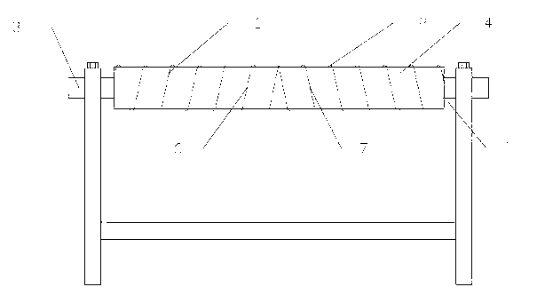
[0011] Such as figure 1 , figure 2 As shown, a film flattening roller provided in this embodiment includes a roller 1, ribs 2 and a rotating shaft 3. Ribs 2 are provided on the surface 4 of the roller 1, and ribs 2 are arranged at both ends 5 of the roller 1. There are rotating shaft 3. In order to make the film product pass smoothly and smoothly, the rib 2 is composed of a left spiral rib 6 and a right spiral rib 7, and the left spiral rib 6 and the right spiral rib 7 are distributed on the surface of the drum 1 in a spiral shape 4 on. Preferably, the rib 2 is welded on the surface 4 of the drum 1 by a round steel wire 8 .

Embodiment 2

[0013] In this embodiment, under the same conditions as in Embodiment 1, the ribs 2 are welded on the surface 4 of the drum 1 by ten round steel wires 8 .


PUM


Abstract

The invention discloses a thin film flattening roller. The thin film flattening roller comprises a roller, a convex rib and rotating shafts, wherein the convex rib is arranged on the surface of the roller; and the rotating shafts are arranged at the two ends of the roller. For the fluent and smooth delivery of a thin film product, the convex rib comprises a left spiral convex rib and a right spiral convex rib which are spirally distributed on the surface of the roller. Preferably, the convex rib is formed by welding more than one circular steel wire on the surface of the roller. The thin film flattening roller is very simple in structure and low in cost, effectively avoids the folding and improves the productivity effect of the product.

Description

technical field [0001] The invention relates to a roller, in particular to a film flattening roller. Background technique [0002] At present, EPE film usually needs to be packaged in rolls after the production is completed, but during the transmission process of EPE film, due to the thin thickness of EPE film, it is easy to wrinkle, which makes the roll packaging uneven or difficult to arrange and pack. Production has brought great difficulties, but also greatly affected the benefits of production. Contents of the invention [0003] The object of the present invention is to provide a film flattening cylinder with a very simple structure and less prone to wrinkle phenomenon in order to solve the above technical deficiencies. [0004] In order to achieve the above purpose, the present invention designs a film flattening roller, which includes a roller, ribs and a rotating shaft. The surface of the roller is provided with ribs, and the rotating shafts are arranged at both e...

Claims


Application Information

Patent Timeline
Patent Type & Authority Applications(China)
IPC IPC(8): B65H23/34
Inventor 陈棋伟
Owner 陈棋伟
Features
  • R&D
  • Intellectual Property
  • Life Sciences
  • Materials
  • Tech Scout
  • Unparalleled Data Quality
  • Higher Quality Content
  • 60% Fewer Hallucinations
Learn More