Concrete-filled rectangular steel tube column-box girder full-bolt connection node and construction method

A technology of rectangular steel pipe and concrete column, applied in the direction of building, building structure, etc., can solve the problems of tearing damage at the connection between the inner clapboard and the column wall, large welding residual stress of the column wall, weak parts at the welding seam connection, etc. To achieve the effect of convenient and fast construction technology, to meet the structural bearing capacity and normal use, and to have a clear force transmission

Active Publication Date: 2013-03-27
TIANJIN UNIV
View PDF7 Cites 16 Cited by
  • Summary
  • Abstract
  • Description
  • Claims
  • Application Information

AI Technical Summary

Problems solved by technology

[0014] 1 The joint adopts the form of an inner partition, the inner side of the column wall is welded with the inner partition, and the outer side of the column wall is welded with the short box girder. There are multiple weldings at the same position of the column wall, which weakens the column wall and causes great damage to the column wall. The Northridge earthquake in the United States and the Hanshin earthquake in Japan show that under the action of earthquakes, the joint between the inner diaphragm and the column wall is prone to tearing and damage, which affects the performance of the joints.
[0015] 2) This joint includes three field welds (welds between the upper flange of the short box girder and the upper cover plate, welds between the upper flange of the box girder and the upper cover plate, and welds between the lower flange of the box girder and the lower flange of the short box girder). The labor cost is reduced, and the construction period is prolonged. On the other hand, the welding quality is affected by many factors (welder technology, surrounding environment, electrode quality, etc.), which makes it easy to form weak parts at the weld joint

Method used


Image

  • Concrete-filled rectangular steel tube column-box girder full-bolt connection node and construction method
  • Concrete-filled rectangular steel tube column-box girder full-bolt connection node and construction method
  • Concrete-filled rectangular steel tube column-box girder full-bolt connection node and construction method

Examples


Embodiment Construction

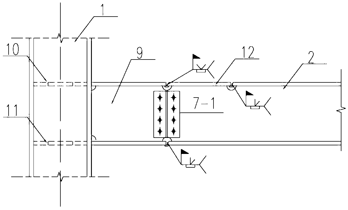
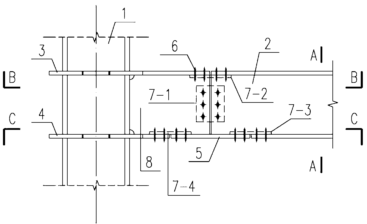
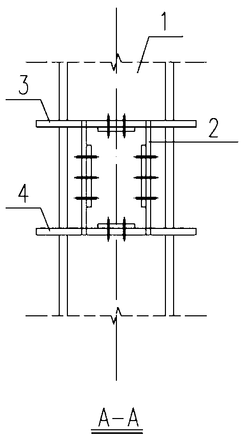
[0038] The present invention proposes a rectangular steel tube concrete column box girder full-bolt connection node, which is characterized in that it includes a rectangular steel tube concrete column 1, a box girder 2, an upper through partition 3, a lower through partition 4, a lower cover 5, and a high-strength Bolts 6, connecting plates 7, and shear plates 8 are composed of the following methods:

[0039] The upper through partition 3 and the lower through partition 4 run through the column wall of the rectangular steel tube concrete column 1, and are connected with the steel tube column wall of the rectangular steel tube concrete column 1 by cut welds. At the position corresponding to the rectangular steel tube concrete column 1 and the web plate of the box girder 2, two shear plates 8 are connected by a cut-out weld. The upper flange of the box girder 2 and the upper through partition 3 are connected by a connecting plate 72 arranged inside the box girder 2 with high-str...


PUM


Abstract

The invention belongs to the technical field of building structure engineering, and relates to a concrete-filled rectangular steel tube column-box girder full-bolt connection node. The concrete-filled rectangular steel tube column-box girder full-bolt connection node comprises a concrete-filled rectangular steel tube column, a box girder, an upper run-through clapboard, a lower run-through clapboard, a lower cover plate, a plurality of high-strength bolts, a plurality of connection plates and two shear plates. The upper run-through clapboard and the lower run-through clapboard penetrate through a concrete-filled rectangular steel tube column wall and are welded with the surrounding of the steel tube column wall of the concrete-filled rectangular steel tube column; the two webs of the box girder are welded together with the groove of the concrete-filled rectangular steel tube column via one shear plate respectively; the upper flange of the box girder is connected with the upper run-through clapboard by the high-strength bolts via the connection plates arranged in the box girder; the two webs of the box girder and the two shear plates are connected by the high-strength bolts via the connection plates arranged in the box girder respectively; and one end of the lower cover plate is connected with the lower flange of the box girder via the connection plate, and the other end of the lower cover plate is connected with the lower flange of the lower run-through clapboard via the connection plate. The invention provides a construction method for the node aforementioned simultaneously. The node and the construction method disclosed by the invention have the advantages of being convenient, fast, and easy to realize.

Description

technical field [0001] The invention belongs to the technical field of building structure engineering and relates to a steel pipe concrete column box girder connecting node. Background technique [0002] The frame column section that makes up the steel frame structure usually adopts H-shaped steel section or box section. Frame columns using H-shaped steel sections, because H-shaped steels have strong and weak axial moments of inertia in section performance, the orientation of H-shaped steels should be such that the strong axis corresponds to the direction of the larger bending moment of the column, or corresponds to the direction of the column The direction in which the calculated length is larger. The box-section column welded by four steel plates has the same inertia axis in the two main axis directions, and there is no distinction between the strong axis and the weak axis, making it especially suitable when the bending distance in the two directions is not much different...

Claims


Application Information

Patent Timeline
Patent Type & Authority Applications(China)
IPC IPC(8): E04B1/58
Inventor 陈志华秦颖王小盾杜颜胜
Owner TIANJIN UNIV
Why Eureka
Try Eureka