Polished rod sealer facilitating taking out sealing element for oil pumping well

A polished rod sealer and seal technology, which is used in sealing/isolation, earthwork drilling, wellbore/well components, etc., can solve the problems of long downtime, increased workover costs, and difficulty in removing old seals. The effect of high success rate of well opening, reduction of workover costs and significant economic benefits

Inactive Publication Date: 2013-03-27
张海峰
View PDF5 Cites 0 Cited by
  • Summary
  • Abstract
  • Description
  • Claims
  • Application Information

AI Technical Summary

Problems solved by technology

[0002] In oil well pumping, the pumping unit drives the polished rod, the sucker rod, and the pump to reciprocate up and down to realize oil pumping. Since the pumping system is closed, the crude oil pumped out has a certain pressure, so the polished rod must be inside the polished rod sealer. Reciprocating up and down, the polished rod sealer hugs the polished rod tightly, the seals in the polished rod sealer are easily damaged, and the seals need to be replaced frequently. When replacing, stop the well first, then take out the old seals, and then install new seals. Due to the structure and working environment of the polished rod sealer, the polished rod is inside it, the gap between the polished rod and the sealing box is small, and it is difficult to take out the old seal. The old seals take a long time, and the oil well shuts down for a long time. For heavy oil wells and sand producing oil wells, it will be difficult to restart the well after a long shutdown time. Many oil wells cannot be opened, which will increase the workover cost and cause great economic losses.

Method used


Image

  • Polished rod sealer facilitating taking out sealing element for oil pumping well

Examples


Embodiment Construction

[0008] Embodiments of the present invention will be described below in conjunction with the accompanying drawings.

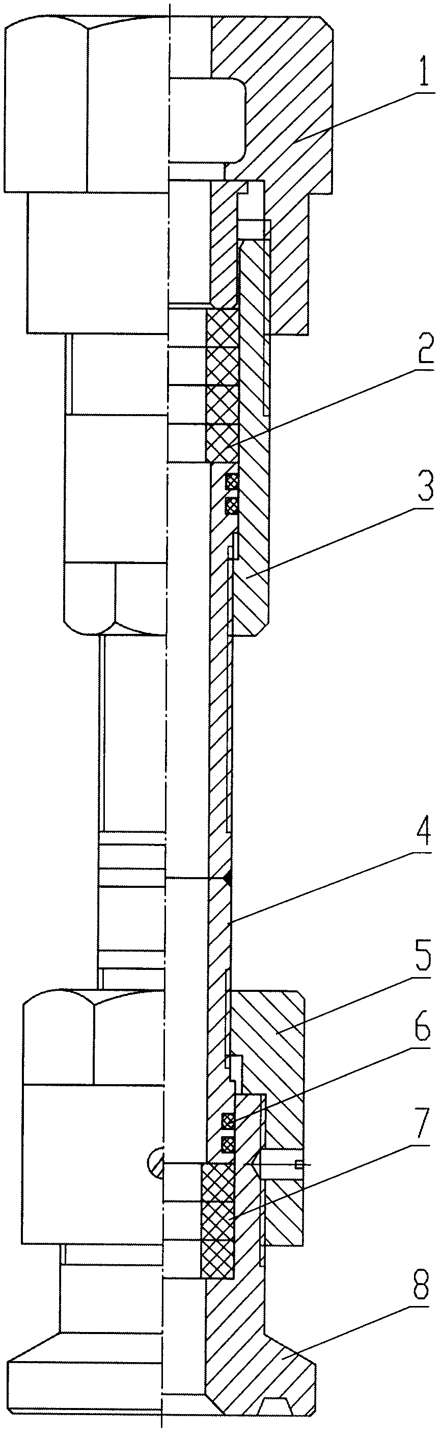
[0009] As can be seen from the figure, the embodiment of the present invention includes an adjustment cap 1, a sealing member 2, a sealing box 3, a support pipe 4, a connecting sleeve 5, a sealing ring 6, a blowout-proof sealing member 7, and a connecting head 8. The sealing member 2 is installed on the sealing Inside the box 3, the thread of the adjusting cap 1 is screwed with the thread of the sealing box 3, the end of the support tube 4 is in the sealing box 3, the seal 2 sits on the upper end surface of the support tube 4, and the sealing can be adjusted by rotating the adjusting cap 1 The tightness of part 2, the upper thread of support pipe 4 is a left-handed thread, the lower thread of sealing box 3 is a left-handed thread, and the upper thread of support pipe 4 matches the lower thread of sealing box 3 and is screwed together.

[0010] In order not to re...


PUM


Abstract

The invention discloses a polished rod sealer facilitating taking out a sealing element for an oil pumping well, wherein the sealing element is installed in a sealing box; the thread of an adjusting cap is screwed with the thread of the sealing box; the end part of a support tube is located in the sealing box; the sealing element is located on the upper end surface of the support tube; the upper thread of the support tube is a left-hand thread; the lower thread of the sealing box is a left-hand thread; the upper thread of the support tube is matched and screwed with the lower thread of the sealing box; a blowout-preventing sealing element is installed in a connecting head; the upper thread of the connector is connected with the lower thread of a connecting sleeve; the lower thread of the support tube is a left-hand thread; the upper thread of the connecting sleeve is a left-hand thread; the lower thread of the support tube is matched and screwed with the upper thread of the connecting sleeve; the lower part of the support tube is inserted in the connector; the lower end surface of the support tube presses the blowout-preventing sealing element; and a sealing ring is installed between the support tube and the connector. The polished rod sealer facilitates taking out the old sealing element, is short in the production halt time of an oil well, capable of reducing or eliminating the influence of thick oil and sand production on the re-opening of the oil well, high in well opening success rate, reduced in well repair expense, and remarkable in economic benefits.

Description

technical field [0001] The invention relates to the well head equipment of an oil pumping well in an oil field, and is a polished rod sealer for an oil pumping well which is convenient for taking out a sealing member. Background technique [0002] In oil well pumping, the pumping unit drives the polished rod, the sucker rod, and the pump to reciprocate up and down to realize oil pumping. Since the pumping system is closed, the crude oil pumped out has a certain pressure, so the polished rod must be inside the polished rod sealer. Reciprocating up and down, the polished rod sealer hugs the polished rod tightly, the seals in the polished rod sealer are easily damaged, and the seals need to be replaced frequently. When replacing, stop the well first, then take out the old seals, and then install new seals. Due to the structure and working environment of the polished rod sealer, the polished rod is inside it, the gap between the polished rod and the sealing box is small, and it ...

Claims


Application Information

Patent Timeline
Patent Type & Authority Applications(China)
IPC IPC(8): E21B33/03
Inventor 张海峰
Owner 张海峰
Why Eureka
Try Eureka