Supercharge Your Innovation With Domain-Expert AI Agents!

System and method for damping combustor nozzle vibrations

A technology of vibration attenuation and burners, which is applied in the direction of combustion methods, burners, gas fuel burners, etc., and can solve problems such as attenuation and difficult vibration

Active Publication Date: 2013-03-27
GENERAL ELECTRIC CO
View PDF4 Cites 0 Cited by
  • Summary
  • Abstract
  • Description
  • Claims
  • Application Information

AI Technical Summary

Problems solved by technology

Design gaps between nozzle and support structure to allow for thermal growth and manufacturing tolerances make vibration damping difficult

Method used


Image

  • System and method for damping combustor nozzle vibrations
  • System and method for damping combustor nozzle vibrations
  • System and method for damping combustor nozzle vibrations

Examples


Embodiment Construction

[0043] Reference will now be made in detail to embodiments of the invention, one or more examples of which are illustrated in the accompanying drawings. The detailed description uses numerical and letter designations to refer to features in the drawings. The same or similar symbols in the drawings and description are used to designate the same or similar parts of the present invention.

[0044] Each example is provided by way of explanation of the invention, not limitation of the invention. In fact, it will be apparent to those skilled in the art that modifications and variations can be made in the present invention without departing from the scope or spirit of the invention. For example, features illustrated or described as part of one embodiment can be used on another embodiment to yield a still further embodiment. Thus, it is intended that the present invention covers such modifications and variations as come within the scope of the appended claims and their equivalents. ...


PUM


Abstract

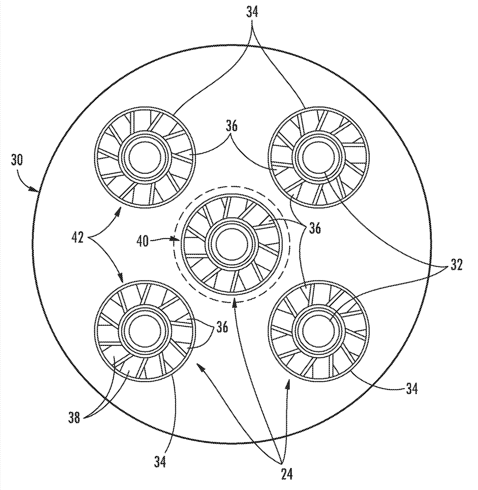
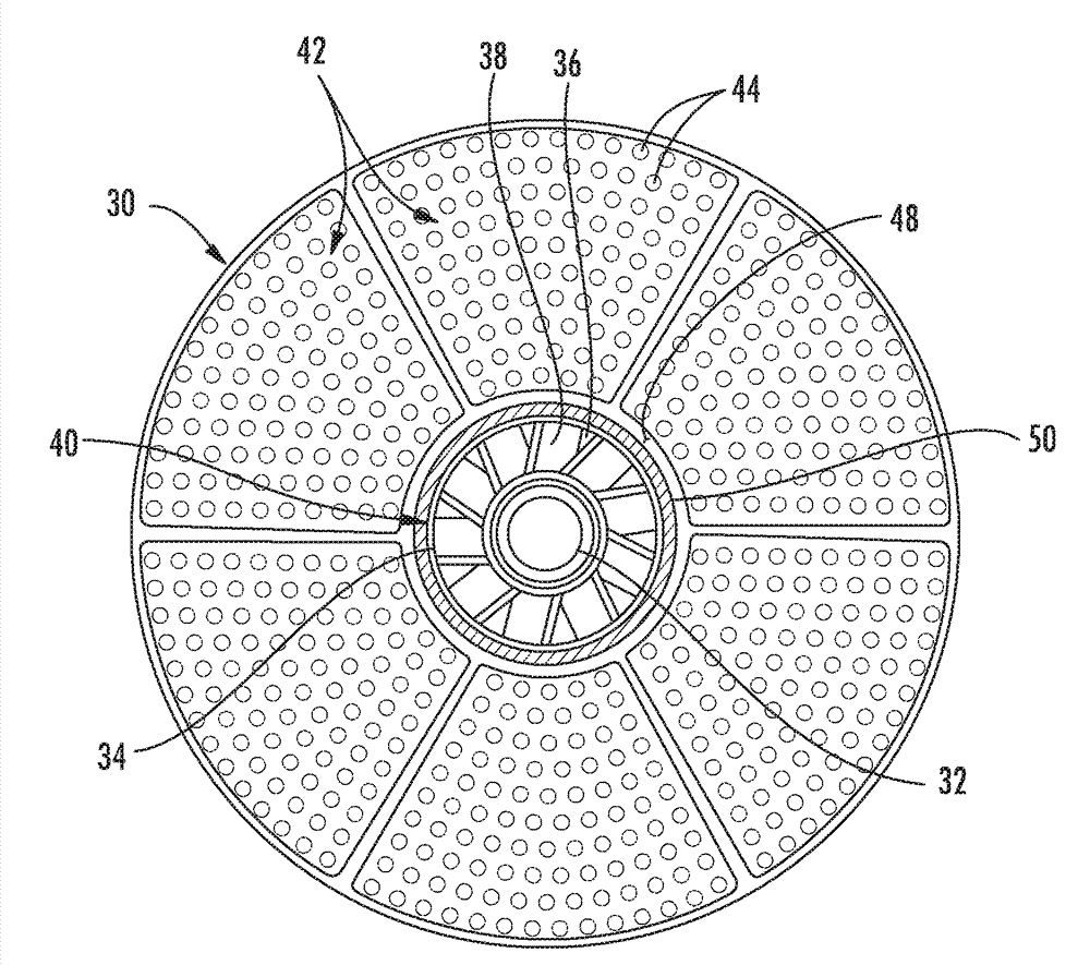
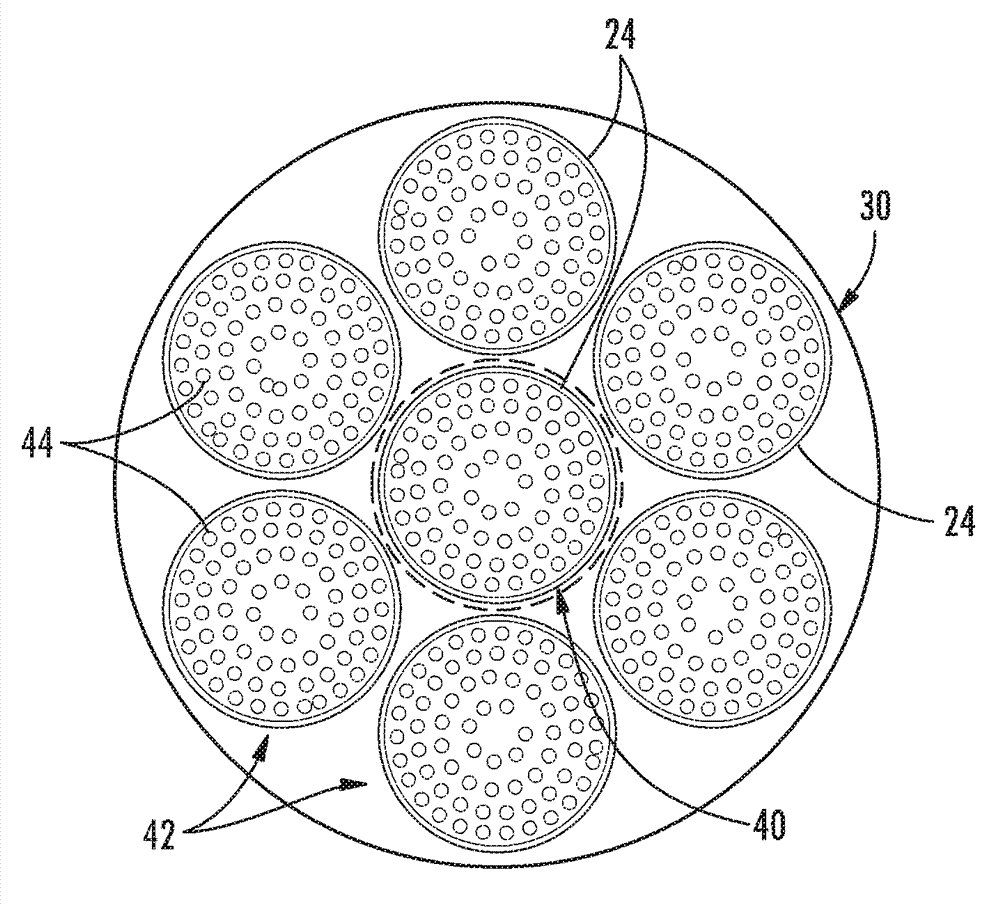
The invention relates to a system and a method for damping combustor nozzle vibrations. The system for damping combustor nozzle vibrations includes an end cover and a combustion chamber downstream from the end cover. First and second sets of nozzles (40, 42) extend axially between the end cover (14) and the combustion chamber. The second set of nozzles (42) is adjacent to the first set of nozzles (40). The system includes means (50) for damping vibrations between the nozzles (40, 42) with a gap (48) between the means for damping vibrations and the second set of nozzles (42). A method for damping combustor nozzle vibrations includes flowing a working fluid through first and second sets of nozzles (40, 42), wherein the first set of nozzles (40) includes a damping member (50) attached to and circumferentially surrounding at least a portion of the first set of nozzles (40), and contacting at least one nozzle in the second set of nozzles (42) with the damping member (50) on at least one nozzle (24) in the first set of nozzles (40).

Description

technical field [0001] The present invention generally relates to systems and methods for damping combustor nozzle vibrations. Background technique [0002] Combustors are commonly used in industrial and power generation operations to ignite fuel to produce combustion gases having high temperature and pressure. For example, gas turbines typically include one or more combustors to generate power or thrust. A typical gas turbine used to generate electricity includes an axial compressor at the front, one or more combustors near the middle, and a turbine at the rear. Ambient air may be supplied to the compressor, and the rotating blades and stationary vanes in the compressor gradually impart kinetic energy to the working fluid (air) to produce a compressed working fluid in a high energized state. Compressed working fluid exits the compressor and flows through one or more nozzles into a combustion chamber in each combustor where it mixes with fuel and ignites to produce combust...

Claims


Application Information

Patent Timeline
Patent Type & Authority Applications(China)
IPC IPC(8): F23D11/38F23D14/48
CPCF23R3/34F23R3/10F23R3/286F23R3/16F23R2900/00014F23M99/005F23M20/005
Inventor K.C.贝索姆B.J.巴丁
Owner GENERAL ELECTRIC CO
Features
  • R&D
  • Intellectual Property
  • Life Sciences
  • Materials
  • Tech Scout
  • Unparalleled Data Quality
  • Higher Quality Content
  • 60% Fewer Hallucinations
Learn More