Automatic discharge device of calcium carbide furnace

A furnace device, calcium carbide furnace technology, applied in furnaces, furnace components, charge control, etc., can solve problems such as failure to meet the use requirements of calcium carbide furnaces, difficulty in passing molten calcium carbide, difficulty in controlling the depth of blockage, etc., to achieve normal operation of the furnace mouth, Reduce adverse effects and block eyesight

Active Publication Date: 2014-08-06
DALIAN HUARUI HEAVY IND GRP CO LTD
View PDF7 Cites 0 Cited by
  • Summary
  • Abstract
  • Description
  • Claims
  • Application Information

AI Technical Summary

Problems solved by technology

[0003] 1. In the operation of manual eye opening, since the diameter of the steel bar used to poke the hole is only about 20mm, the hole that is poked out is small, it is difficult for the molten calcium carbide to pass through, and the furnace mouth is easy to block;
[0004] 2. When manually plugging furnace holes, the depth of the plugging is difficult to control
If the blockage is too deep, it will lead to eye-running accidents;
[0005] 3. The labor intensity of workers is high during manual operation, the working environment is harsh, and the manual participation time in the whole process is very long, there are great potential safety hazards, and various personal injuries are prone to occur
[0006] Although domestic submerged arc furnaces have also appeared in the furnace, most of them have unreasonable structures, inconvenient operation, and poor stability. They can only be used for general submerged arc furnaces, and cannot meet the requirements of calcium carbide furnaces

Method used


Image

  • Automatic discharge device of calcium carbide furnace
  • Automatic discharge device of calcium carbide furnace
  • Automatic discharge device of calcium carbide furnace

Examples


Embodiment Construction

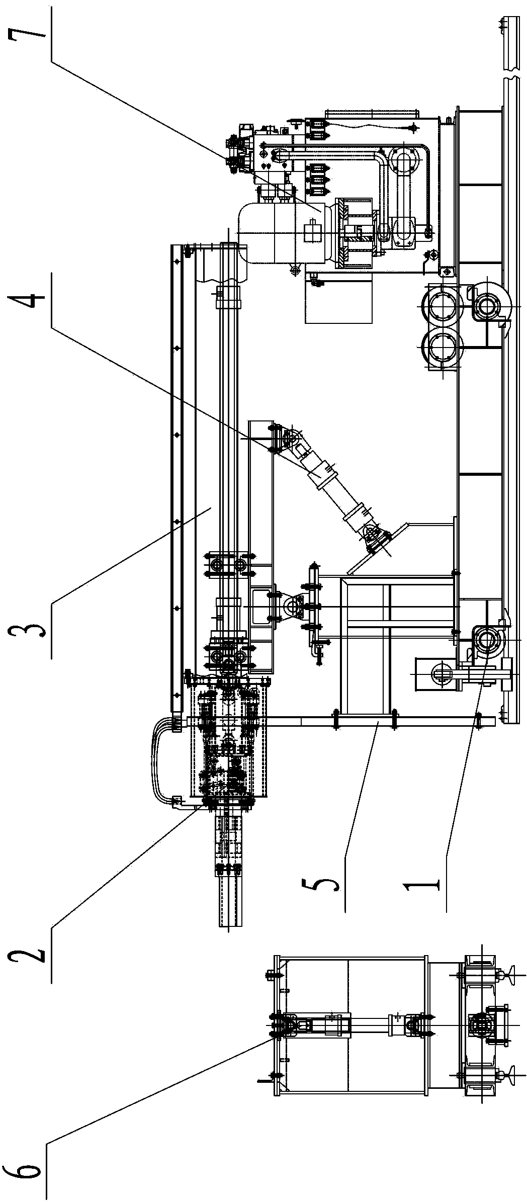
[0034] Such as figure 1 The automatic furnace discharge device of a calcium carbide furnace shown is composed of a cart mechanism 1, a tool lever locking mechanism 2, a working arm mechanism 3, a working arm tilting mechanism 4, a heat insulation protection system 5, a tool cart 6 and a calcium carbide furnace for controlling The on-board hydraulic station 7 of the hydraulic equipment in the automatic furnace discharge device and the automatic control system 8 for the structural cooperation of the various parts of the calcium carbide furnace automatic furnace discharge device are composed; wherein the tool lever locking mechanism 2 and the working arm mechanism 3 are connected together by bolts, The working arm mechanism 3 is fixed to the upper part of the cart mechanism 1 by bolts. The two ends of the working arm tilt mechanism 4 are respectively connected with the cart mechanism 1 and the working arm mechanism 3 by bolts. The heat insulation protection system 5 is fixed at the ...


PUM


Abstract

The invention discloses an automatic discharge device of a calcium carbide furnace. The automatic discharge device comprises a cart mechanism, a tool rod locking mechanism, a working arm mechanism, a working arm pitching mechanism, a heat insulation protection system, a tool trolley, a trolley hydraulic station used for controlling a hydraulic device in the automatic discharge device of the calcium carbide furnace, and an automatic control system used to work together with all parts of the automatic discharge system of the calcium carbide furnace, wherein the tool rod locking mechanism and the working arm mechanism are connected together through a bolt, the working arm mechanism is fixed on the upper part of the cart mechanism through a bolt, two ends of the working arm pitching mechanism are respectively combined with the cart mechanism and the working arm mechanism through bolts, the heat insulation protection system is fixed on the front end of the cart mechanism, and the trolley hydraulic station is fixed on the back of the upper part of the cart mechanism. According to the automatic discharge device adopting the scheme, the whole automatic discharge device adopts hydraulic transmission and can be operated in a long distance, thus the manual operation of a hearth attendant is greatly reduced, the hearth attendant is prevented from being in a high-temperature environment for a long time, and the potential safety hazard is reduced.

Description

Technical field [0001] The invention belongs to smelting equipment, which is used to automatically discharge a calcium carbide furnace. Background technique [0002] The firing operation of the calcium carbide furnace (mainly opening, poke, and plugging) has always been manual operation. In the production of small calcium carbide furnaces in the past, the abnormality of the furnace door during manual operation has little effect on the production, but for large calcium carbide furnaces Furnace production is different. Manual operation often causes difficulties, and even accidents affect production. There are also the following shortcomings for manual production of large calcium carbide furnaces: [0003] 1. In the operation of artificial eye opening, since the diameter of the steel bar used to poke the eye is only about 20mm, the hole of the poke is small, it is difficult for the molten carbide to pass, and the furnace mouth is easy to block; [0004] 2. When manually plugging the f...

Claims


Application Information

Patent Timeline
Patent Type & Authority Patents(China)
IPC IPC(8): F27D3/15
Inventor 胡子瑞杨林王楠丛建
Owner DALIAN HUARUI HEAVY IND GRP CO LTD
Why Eureka
Try Eureka