Method and device for calibrating R wave of electrocardiosignal

A technology of ECG signal and calibration method, which is applied in the field of biomedical information engineering, can solve problems such as non-R calibration, R wave error, and less R wave calibration, so as to eliminate missed detection and false detection, with obvious effect and wide application prospect Effect

Active Publication Date: 2014-05-28
CHONGQING UNIV OF POSTS & TELECOMM
View PDF6 Cites 0 Cited by
  • Summary
  • Abstract
  • Description
  • Claims
  • Application Information

AI Technical Summary

Problems solved by technology

Since these three waves are closely connected and the total time does not exceed 0.10 seconds, they are collectively called QRS waves. The time occupied by QRS represents the time required for the propagation of ventricular muscle excitation. For normal people, it is between 0.06 and 0.10 seconds, and usually through R waves. To characterize the QRS complex wave, it was indicated during the project implementation that after identifying the R wave through some existing methods, there may be errors (such as missing or false detection) in the identified R wave due to factors such as interference. (such as missed detection or false detection) has a great impact on the detection of other subsequent waves (such as P wave, T wave, Q wave and S wave, S-T segment) and subsequent ECG analysis
[0003] There are many existing technologies on QRS detection. For example, Chinese invention patent 201010214626.4 provides a method for detecting R wave peaks of ECG signals. This is a technology for QRS wave detection, but there are few existing technologies related to R wave calibration. Although China Invention patent 201010214626.4 An electrocardiogram R wave detection method mentions eliminating false R points and correcting false points. This is only determined by the characteristics of its R recognition and detection algorithm, not the real R calibration, and cannot be used independently of the algorithm.

Method used


Image

  • Method and device for calibrating R wave of electrocardiosignal
  • Method and device for calibrating R wave of electrocardiosignal
  • Method and device for calibrating R wave of electrocardiosignal

Examples


Embodiment Construction

[0056] In order to make the purpose, technical solutions and advantages of the present invention clearer, the present invention will be further described in detail below in conjunction with the accompanying drawings. Obviously, the described embodiments are only some of the embodiments of the present invention, rather than all of them. Based on the embodiments of the present invention, all other embodiments obtained by persons of ordinary skill in the art without making creative efforts belong to the protection scope of the present invention.

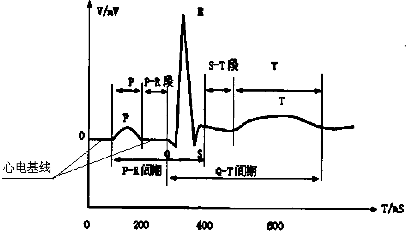
[0057] The present invention assumes that the QRS wave recognition has been successful, and the R wave position has been determined in the original ECG data, expressed as iR (iR is the position sequence of the R wave, and its length is Lr), but there may be deviations in this position, such as missed detection (QRS is not detected in the place where there is QRS wave), false detection (QRS wave is detected in the place where there is no ...


PUM


Abstract

The invention relates to the field of biomedical engineering and provides a method for calibrating an R wave of an electrocardiosignal. The method comprises the following steps: figuring out a difference between a front R wave position and a back R wave position which are adjacent to each other in original electrocardio data, so as to obtain an R wave interval value sequence; figuring out a forward different parameter and a backward difference parameter of the difference between the R wave positions according to the R wave interval value sequence; detecting whether the position of the R wave fails to detect or not according to the size relation of the difference between the front R wave position and the back R wave position which are adjacent to each other; supplementing the position of the R wave failing to detect; detecting whether the position of the R wave is virtually detected or not; and deleting the virtually detected position of the R wave. The invention further provides a device for calibrating the R wave of the electrocardiosignal. According to the invention, through the adoption of a relation between the originally detected R wave positions and an electrocardio data value position relation between the two R waves, leaked detection and virtual detection of the R wave are effectively eliminated.

Description

technical field [0001] The invention relates to the field of biomedical information engineering, in particular to a method and device for calibrating R waves of electrocardiographic signals. Background technique [0002] A typical QRS complex consists of three consecutive waves (see figure 1 shown). The first downward wave is the Q wave, followed by the Q wave and a narrow upward wave is the R wave, and another downward wave connected with the R wave is the S wave. Since these three waves are closely connected and the total time does not exceed 0.10 seconds, they are collectively called QRS waves. The time occupied by QRS represents the time required for the propagation of ventricular muscle excitation. For normal people, it is between 0.06 and 0.10 seconds, and usually through R waves. To characterize the QRS complex wave, it was indicated during the project implementation that after identifying the R wave through some existing methods, it may be due to the influence of f...

Claims


Application Information

Patent Timeline
Patent Type & Authority Patents(China)
IPC IPC(8): A61B5/0456A61B5/352
Inventor 曾垂省梁亦龙王允向浏欣赵志强
Owner CHONGQING UNIV OF POSTS & TELECOMM
Why Eureka
Try Eureka