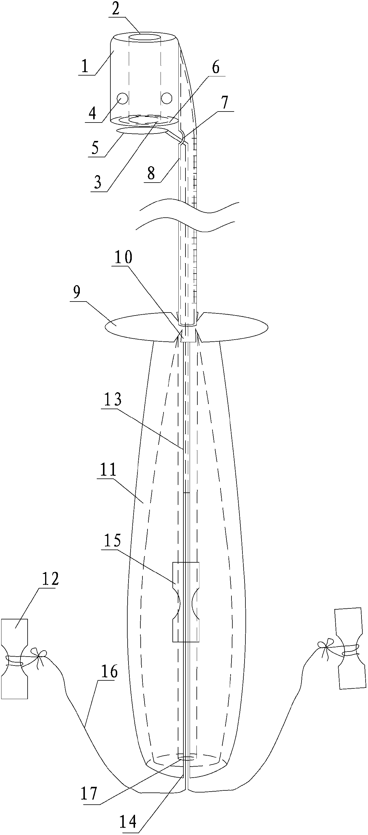
Tendon taking machine

A head and cylindrical technology, applied in the field of tendon extractor and tendon sheath extractor, can solve the problems of high risk, expensive allogeneic tendon, loss of labor ability, etc., so as to shorten the operation time, save the operation time, and reduce the workload. Effect

Active Publication Date: 2014-07-30
王燕杰
View PDF7 Cites 0 Cited by
  • Summary
  • Abstract
  • Description
  • Claims
  • Application Information

AI Technical Summary

Problems solved by technology

The first step in ligament reconstruction with autologous tendon is to use a tendon harvester to harvest the gracilis, semitendinosus or plantar muscles. The existing autologous tendon harvesters in the medical market all over the world use the oval oblique section of the release hole. However, during the operation, because of the existence of such a very sharp blade, it is very risky to use it. Even the most experienced and skilled provincial orthopedic arthroscopic technology leader took the The tendon may be cut off from the middle of the tendon due to hand shaking, encountering the tendon foot, tendon adhesion, excessive resistance when advancing, or unintentional withdrawal. Only half of the tendon can be taken out, and there is not enough length of the tendon. The result is Surgery fails at the first step and subsequent surgical steps cannot be performed
For the chief physicians of local ordinary municipal hospitals, most of them dare not try to take autologous tendon because they are afraid of the huge occupational risks brought by traditional tendon harvesters, and can only buy allogeneic tendon, but allogeneic tendon is not only very expensive , and it is still very scarce. As a result, the above high-level operations cannot be performed routinely in many hospitals. Many patients are forced to transfer or are afraid of the cost of allogeneic tendon, so they give up or delay treatment, which increases the disability rate of joints. Early step into traumatic arthritis or osteoarthritis, loss of working ability, increase the burden on family and society

Method used


Image

  • Tendon taking machine
  • Tendon taking machine

Examples


Embodiment Construction

[0021] In order to make the object, technical solution and advantages of the present invention clearer, the present invention will be further described in detail below in conjunction with the accompanying drawings and embodiments. It should be understood that the specific embodiments described here are only used to explain the present invention, not to limit the present invention.

[0022] Please also refer to figure 1 and figure 2 , which is a structural schematic diagram of the tendon harvester provided by the preferred embodiment of the present invention. The tendon extractor includes a device head 1, a wire 16, a rod body 8, a tiger mouth piece 9 and a handle 11.

[0023] The device head 1 is provided with a cylindrical through hole, and one end of the cylindrical through hole is defined as a separation hole 2, the outer wall of the separation hole 2 is blunt, and one end of the cylindrical through hole is defined as a release hole 3, in the device head 1 A groove 6 is...


PUM


Abstract

The invention discloses a tendon taking machine which comprises a machine head, a rod body and a metal wire. The machine head is provided with a cylindrical through hole; one end of the through hole is a separation hole, and the other end of the through hole is a release hole provided with a groove on the end surface. The rod body is a hollow rod; one end of the hollow rod is fixed on the machine head, and the other end of the hollow rod extends in the direction parallel to the axial direction of the through hole and is an opening end; and a wire penetrating hole is formed on one side of the hollow rod facing the groove. After being bent, a bent part of the metal wire penetrates outside the wire penetrating hole from the opening end to form a metal wire arch with a central angle more than 270 degrees, or surrounds for at least one circle to form a metal wire ring; the metal wire arch or the metal wire ring is accommodated in the groove; and the two bent ends are exposed outside the opening end. The tendon taking machine has the advantage that tendons to be taken are cut off safely and effectively by using the metal wire cutting principle to totally avoid the high risk of accidental cutting off the tendons and hurting nervus vascularis at midway caused by cutting off the tendons through the sharp edge cutting principle in the traditional tendon taking machines.

Description

technical field [0001] The invention relates to a tendon extraction device in the technical field of medical devices, in particular to a tendon extraction device that can be used in orthopedics, plastic surgery, and burns, and is mainly used for minimally invasive extraction of gracilis, semitendinosus, and plantaris in orthopedic operations. Autologous tendon transplantation is used for ligament reconstruction of knee joints such as anterior and posterior cruciate ligament rupture, medial and lateral collateral ligament injury, patellar tendon rupture, patellofemoral ligament injury and contracted Achilles tendon rupture. Background technique [0002] In patients with clinical orthopedic sports trauma or car accident violence, the violence causes the knee joint to twist to generate huge shear and tension, and a single or multiple ligaments of the knee joint are ruptured, such as: rupture of the anterior and posterior cruciate ligaments of the knee joint, rupture of the media...

Claims


Application Information

Patent Timeline
Patent Type & Authority Patents(China)
IPC IPC(8): A61B17/00
Inventor 徐斌王燕杰徐洪港王瑞涂俊吴磊姜少伟
Owner 王燕杰
Why Eureka
Try Eureka