
Static and dynamic exchange-type thighbone interlocking intramedullary nail

An exchange-type, static-dynamic technology, applied in the field of medical devices, can solve problems such as lack of fracture longitudinal stress stimulation at the fracture end, affect fracture healing, and delayed fracture healing, and achieve the effects of increasing effective physiological stimulation, promoting fracture healing, and stress dispersion

Inactive Publication Date: 2013-04-03
SUZHOU RUIHUA HOSPITAL
View PDF5 Cites 5 Cited by
  • Summary
  • Abstract
  • Description
  • Claims
  • Application Information

AI Technical Summary

Problems solved by technology

At present, there are two round holes in the coronal surface of the distal end of common femoral intramedullary nails, which are statically fixed after being locked with locking nails during the operation. There is stress shielding, and the fracture end lacks the longitudinal stress stimulation required for fracture healing, which is likely to cause fractures clinically. Delayed union or even nonunion, resulting in adverse consequences. Even if there is a sliding hole at the proximal end, after taking out the static locking nail and retaining a dynamic nail for dynamization, the fracture end may swing, which affects fracture healing
Sometimes the fracture is close to the proximal end of the femur, and only two static locking screws at the distal end can be removed for dynamization. After the two static locking screws at the distal end can be taken out, the fracture end will inevitably rotate and shift due to the lack of locking screws, which will affect fracture healing. , can form hypertrophic nonunion

Method used


Image

  • Static and dynamic exchange-type thighbone interlocking intramedullary nail
  • Static and dynamic exchange-type thighbone interlocking intramedullary nail
  • Static and dynamic exchange-type thighbone interlocking intramedullary nail

Examples


Embodiment Construction

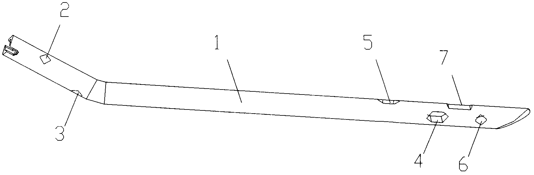
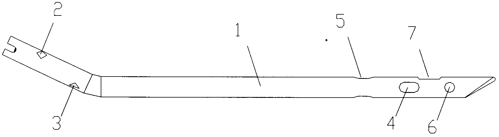
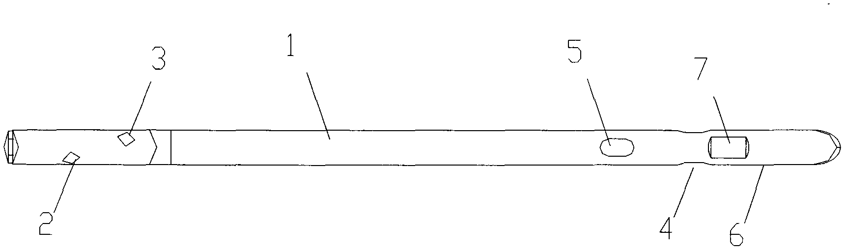
[0025] as attached Figure 1-3 The shown static and dynamic exchange type femoral interlocking intramedullary nail of the present invention includes a nail body 1, and the coronal surface of the distal end of the nail body 1 is provided with a first sliding locking hole 4 and a static force hole 6 , the sagittal plane of the distal end of the nail main body 1 is provided with a second sliding lock hole 5, the first sliding lock 4 holes and the second sliding locking hole 5 are elongated holes; the static force hole 6 is arranged at the second The distal end of a sliding locking hole 4 and the second sliding locking hole 5, and at the distal end of the nail main body 1; the proximal end of the nail main body 1 is provided with a first fixing hole 2 and a second fixing hole 3; The first fixing hole 2 and the second fixing hole 3 are arranged on mutually perpendicular surfaces; the length of the first sliding locking hole 4 is shorter than the second sliding locking hole 5; the s...


PUM


Abstract

The invention discloses a static and dynamic exchange-type thighbone interlocking intramedullary nail, which comprises a nail main body. A static hole and a first sliding locking hole are arranged on the coronal surface of the far end of the nail main body. A second sliding locking hole is arranged on the sagittal surface of the far end of the nail main body. The first sliding locking hole and the second sliding locking hole are long holes. The static hole is arranged at the far end of the first sliding locking hole and the second sliding locking hole and is arranged at the end part of the far end of the nail main body. Due to the static and dynamic exchange-type thighbone interlocking intramedullary nail, according to the actual situation of fracture healing, early-stage static fixation can be realized, a far-end static locking nail can be taken out to implement dynamic fixation if a fracture is not well healed, static fixation is realized after the first sliding locking hole is in place, a sliding locking nail in place is taken out if the fracture is not healed ideally, dynamic fixation is implemented through a second sliding locking nail, then static fixation is achieved, controllable adjustment of repetitive dynamic and static exchange fixation can be realized and the fracture healing is better promoted.

Description

technical field [0001] The present invention relates to an intramedullary nail, in particular to an intramedullary nail that can achieve early static fixation of the bone, and can be dynamized. The utility model relates to a static and dynamic exchange type femoral interlocking intramedullary nail for controllable adjustment of dynamic and static fixation so as to promote fast healing of fractures, and belongs to the technical field of medical devices. Background technique [0002] Locking intramedullary nails are currently the mainstream internal fixation equipment for the treatment of long tubular bone fractures in the field of orthopedics. They overcome the shortcomings of ordinary intramedullary nails in their poor torsion resistance, and are the direction of development in the treatment of bone shaft fractures. It can effectively prevent the shortening of fracture ends, has the advantages of strong torsion resistance, small stress shielding effect, strong fixation, and ...

Claims


Application Information

Patent Timeline
IPC IPC(8): A61B17/72
Inventor 刘德俊
Owner SUZHOU RUIHUA HOSPITAL
Learn More