
Device for cleaning megasonic transducer

A technology of transducers and megasonic waves, applied in chemical instruments and methods, cleaning methods and utensils, cleaning methods using liquids, etc., can solve the problems of slow cleaning speed, poor cleaning quality, and low efficiency, and achieve high cleaning efficiency , good cleaning effect, uniform and comprehensive cleaning effect

Active Publication Date: 2013-04-03
BEIJING SEVENSTAR ELECTRONICS CO LTD
View PDF12 Cites 3 Cited by
  • Summary
  • Abstract
  • Description
  • Claims
  • Application Information

AI Technical Summary

Problems solved by technology

In the prior art, a simple water tank is used to clean the megasonic transducer. This method has low efficiency, slow cleaning speed and poor cleaning quality.

Method used


Image

  • Device for cleaning megasonic transducer
  • Device for cleaning megasonic transducer
  • Device for cleaning megasonic transducer

Examples


Embodiment Construction

[0023] The specific implementation manners of the present invention will be further described in detail below in conjunction with the accompanying drawings and embodiments. The following examples are used to illustrate the present invention, but are not intended to limit the scope of the present invention.

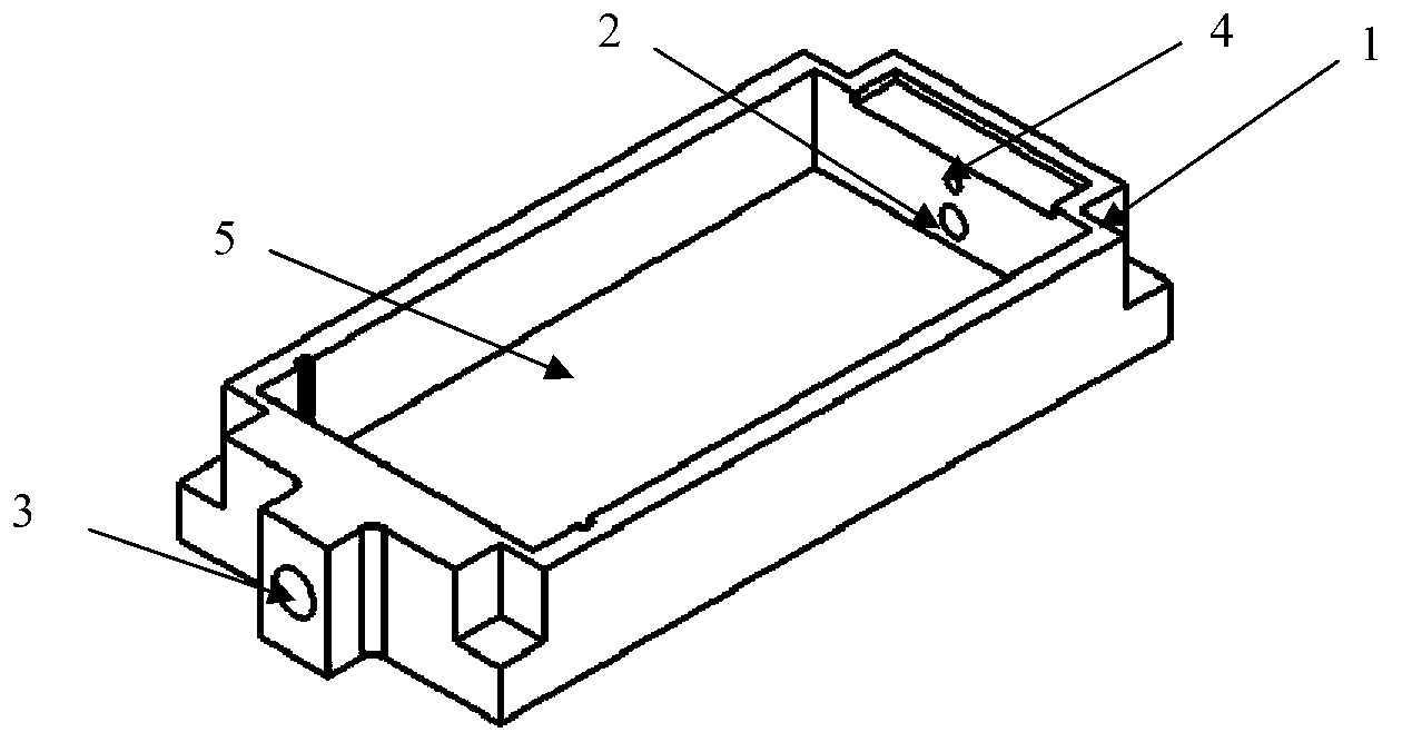
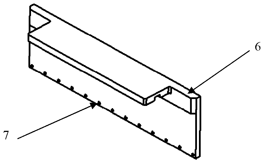
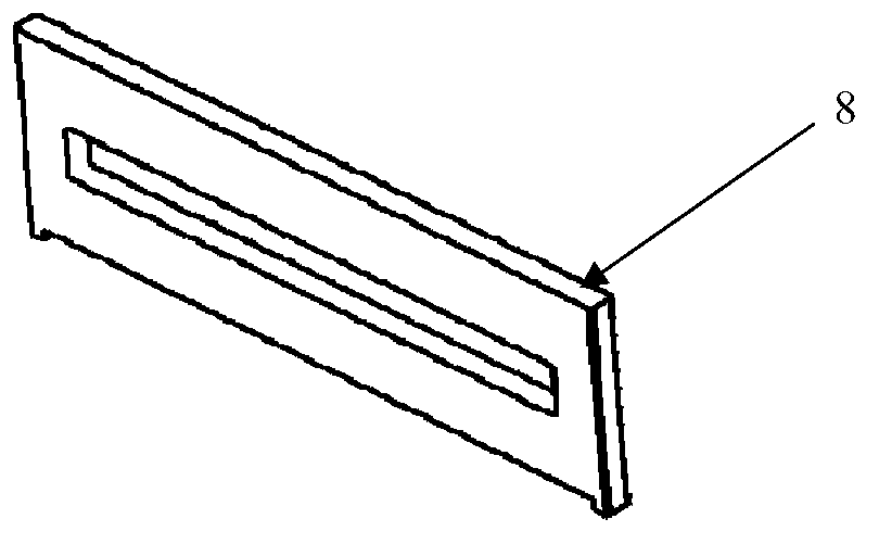
[0024] In the embodiment of the present invention, a trough-type device is used to clean the megasonic transducer. The cleaning device includes a cleaning tank, a baffle and a flow partition, and the baffle and the flow partition are respectively arranged on the liquid inlet side and the liquid outlet of the cleaning tank. side. The cleaning liquid is rapidly flowed through the megasonic transducer to be cleaned, where the cleaning liquid may be pure water.

[0025] The cleaning tank is a quadrilateral tank structure, and a liquid inlet and a liquid outlet are provided on one side and the opposite side of the cleaning tank, and the liquid outlet is larger than the liquid ...


PUM


Abstract

The invention discloses a device for cleaning a megasonic transducer, which comprises a cleaning tank, a flow-retard plate and a flow-separation plate, wherein a liquid inlet and a liquid outlet are respectively and correspondingly formed on two sides of the cleaning tank; a gas inlet is formed on the side of the liquid inlet side; the flow-retard plate is arranged in the cleaning tank and in front of the liquid inlet; a plurality of drainage holes are formed at the bottom of the flow-retard plate; the flow-separation plate is arranged in the cleaning tank and in front of the liquid outlet; a gaps is formed between the bottom of the flow-separation plate and the bottom surface of the clean water tank; and a hole for discharging excessive liquid in the cleaning tank is formed on the flow-separation plate. The device provided by the invention can quickly perform mechanized cleaning for the megasonic transducer at high efficiency and good effect in a uniform and all-sided manner.

Description

technical field [0001] The invention relates to the field of equipment cleaning, in particular to a device for cleaning a megasonic transducer. Background technique [0002] Megasonic transducers have many advantages and are widely used in cleaning equipment in the semiconductor field. During the cleaning process, the distance between the working surface of the megasonic transducer and the wafer surface is very small (about 1~3mm), which causes the particulate matter on the wafer surface to easily adhere to the bottom surface and bottom side of the megasonic transducer. After a working stroke is finished, the working surface needs to be rinsed, so as not to affect the subsequent cleaning, so as to ensure the cleaning quality of the next wafer. In the prior art, a simple water tank is used to clean the megasonic transducer. This method has low efficiency, slow cleaning speed and poor cleaning quality. Contents of the invention [0003] (1) Technical problems to be solved ...

Claims


Application Information

Patent Timeline
IPC IPC(8): B08B3/04
Inventor 姬丹丹王波雷李伟张享倩王浩
Owner BEIJING SEVENSTAR ELECTRONICS CO LTD
Learn More