Automatic welding equipment for double annular welding beads

An automatic welding and welding bead technology, which is applied in welding equipment, auxiliary welding equipment, welding/cutting auxiliary equipment, etc., can solve the problems of high maintenance costs, poor working conditions, and high requirements for the accuracy of fixtures with the skill level of operators.

Active Publication Date: 2015-05-27
长城汽车股份有限公司平湖分公司
View PDF5 Cites 0 Cited by
  • Summary
  • Abstract
  • Description
  • Claims
  • Application Information

AI Technical Summary

Problems solved by technology

When the robot welding method is used, it needs to be driven by multiple servo motors, and the welding assembly of the workpiece is realized through the PLC system program control. Therefore, the requirements for the skill level of the operator and the precision of the fixture are relatively high; in addition, the robot welding method also has equipment purchases. and high maintenance costs
When manual welding is used, the operator needs to hold the welding cap with the left hand and the welding torch with the right hand, and has to bend down to operate, which has the disadvantages of poor working conditions, high labor intensity, and low work efficiency. At the same time, the consistency of workpiece welding Difficult to guarantee, affecting the improvement of product quality

Method used


Image

  • Automatic welding equipment for double annular welding beads
  • Automatic welding equipment for double annular welding beads
  • Automatic welding equipment for double annular welding beads

Examples


Embodiment Construction

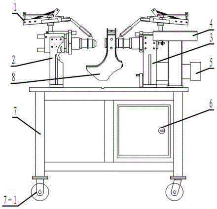
[0030] Referring to Fig. 1, the present invention includes a welding torch position switching and welding torch clamping adjustment mechanism 1, a left positioning mechanism 2, a right positioning mechanism 3, an operation station 4, a power output mechanism 5, a control mechanism 6 and a base platform 7. The welding torch position switching and welding torch clamping adjustment mechanism 1 includes two symmetrical parts, which are respectively assembled with the left positioning mechanism 2 and the right positioning mechanism 3. The left positioning mechanism 2, the right positioning mechanism 3 and the operating station 4 are all fixed on the base platform 7, the power output mechanism 5 is assembled with the right positioning mechanism 3, and the bottom of the base platform 7 is provided with casters 7-1, and the overall equipment can move with the transformation of the working place.

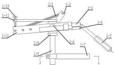
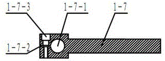
[0031] See Figure 2, image 3 , Figure 4 , the welding torch angle switching and welding...


PUM


Abstract

An automatic welding equipment for double annular welding beads is used for solving problems of high equipment cost, low manual welding efficiency and hardly guaranteed welding quality of a welding robot. The automatic welding equipment comprises a welding gun position switching and welding gun clamping adjusting mechanism, a left side positioning mechanism, a right side positioning mechanism, an operation station, a power output mechanism, a control mechanism and a base stage, wherein the welding gun position switching and welding gun clamping adjusting mechanism comprises a left part and a right part, which are symmetric and respectively mounted together with the left side positioning mechanism and the right side positioning mechanism; the left side positioning mechanism, the right side positioning mechanism and the operation station are all fixed on the base stage; the power output mechanism is mounted together with the right side positioning mechanism; and a caster is arranged at the bottom of the base stage. The automatic welding equipment has the advantages of simple operation, convenient maintenance and low manufacturing cost; the welding efficiency can be increased, the product quality is improved, the welding operation condition is improved and the labor intensities of operators are reduced.

Description

technical field [0001] The invention relates to an automatic welding device, in particular to an automatic welding device suitable for double-sided annular welding bead, and belongs to the technical field of automobiles. Background technique [0002] In automobile manufacturing enterprises, welding is one of the main methods of component assembly. At present, welding operations are generally completed by humans or robots. When the robot welding method is used, it needs to be driven by multiple servo motors, and the welding assembly of the workpiece is realized through the PLC system program control. Therefore, the requirements for the skill level of the operator and the precision of the fixture are relatively high; in addition, the robot welding method also has equipment purchases. and high maintenance costs. When manual welding is used, the operator needs to hold the welding cap with the left hand and the welding torch with the right hand, and has to bend down to operate, ...

Claims


Application Information

Patent Timeline
Patent Type & Authority Patents(China)
IPC IPC(8): B23K37/02B23K37/04
Inventor 李建国刘威王旭陈永科刘丁丁张猛胥媛媛
Owner 长城汽车股份有限公司平湖分公司
Why Eureka
Try Eureka