Floating compression device

A technology of floating compression and compression rod, which is applied in the direction of positioning device, clamping, support, etc., and can solve the problem of fixing the lower part of the workpiece, etc.

Inactive Publication Date: 2013-04-03
重庆市南川区富民科技推广中心
View PDF0 Cites 12 Cited by
  • Summary
  • Abstract
  • Description
  • Claims
  • Application Information

AI Technical Summary

Problems solved by technology

[0004] The present invention intends to provide a floating pressing device

Method used


Image

  • Floating compression device

Examples


Embodiment Construction

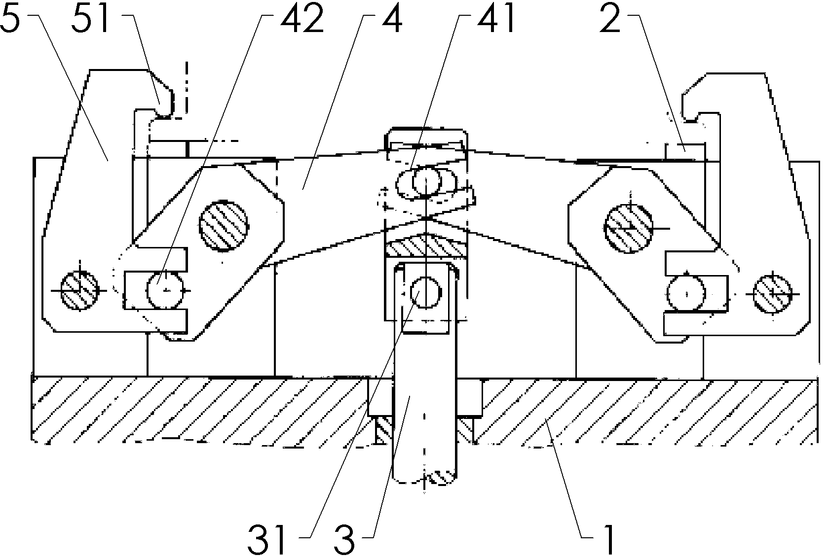
[0010] Such as figure 1 As shown: the floating pressing device in this implementation includes a machine base 1, a fixed support base 2 fixed on the machine base, a force applying rod 3 that can move vertically and axially, a swing rod 4 hinged on the machine base and a hinged On the pressing rod 5 on the machine base, the applying rod is provided with a horizontal applying rod pin 31, and one end of the swing rod is provided with a swing rod chute 41 slidingly matched with the applying rod pin, and the other end of the swing rod is provided with Swing bar pin 42 is arranged, the lower end of hold down bar is provided with the hold down bar chute that slides with swing bar pin, the upper end of hold down bar is provided with hold down block 51 and is positioned at the top of fixed support seat, the upper end of hold down bar , The lower end is located on the same side as the vertical line of the hinged rotation center of the compression rod.

[0011] The working method of thi...


PUM


Abstract

The invention discloses a floating compression device, which is used for solving the problem of fixation of lower supporting legs of workpieces in the prior art. In the scheme, the floating compression device is characterized by comprising a base, fixed supporting seats, a force application rod, swing stems and compression rods, wherein the fixed supporting seats are fixed on the base; the force application rod can move vertically and axially; the swing stems are articulated on the base; the compression rods are articulated on the base; the force application rod is provided with a horizontal force application rod pin; one end of each swing stem is provided with a swing stem sliding chute which is in sliding fit with the force application rod pin; the other end of each swing stem is provided with a swing stem pin; the lower ends of the compression rods are provided with compression rod sliding chutes which are in sliding fit with the swing stem pins; the upper ends of the compression rods are provided with compression blocks, and are positioned above the fixed supporting seat; and the upper and lower ends of the compression rods are positioned on the same side of the articulation rotation center plumb line of the compression rods. The technical scheme is characterized in that lower supporting legs of workpieces can be well fixed.

Description

technical field [0001] The invention relates to a fixture used in machining. Background technique [0002] Machine tool fixtures are indispensable and important process equipment in the machinery manufacturing industry, which can ensure the quality of machining, improve production efficiency, reduce production costs, and reduce labor intensity. [0003] In the actual processing process, the shape and structure of the workpiece are ever-changing. It is a long-term task for workers in the mechanical field to design corresponding fixtures for workpieces with different structures. The clamping and fixing of the lower support feet of the workpiece during processing is one of them. Contents of the invention [0004] The present invention intends to provide a floating pressing device to solve the problem of fixing the lower feet of workpieces in the prior art. [0005] The floating pressing device in this program is characterized in that it includes a machine base, a fixed supp...

Claims


Application Information

Patent Timeline
IPC IPC(8): B23Q3/00
Inventor 袁晴波
Owner 重庆市南川区富民科技推广中心
Why Eureka
Try Eureka