Cam compression clamp

A technology of cams and fixtures, used in clamping, manufacturing tools, supports, etc.

Inactive Publication Date: 2013-04-03
重庆市南川区富民科技推广中心
View PDF0 Cites 6 Cited by
  • Summary
  • Abstract
  • Description
  • Claims
  • Application Information

AI Technical Summary

Problems solved by technology

[0004] The present invention intends to provide a cam pressing fixture to solve the

Method used


Image

  • Cam compression clamp

Examples


Embodiment Construction

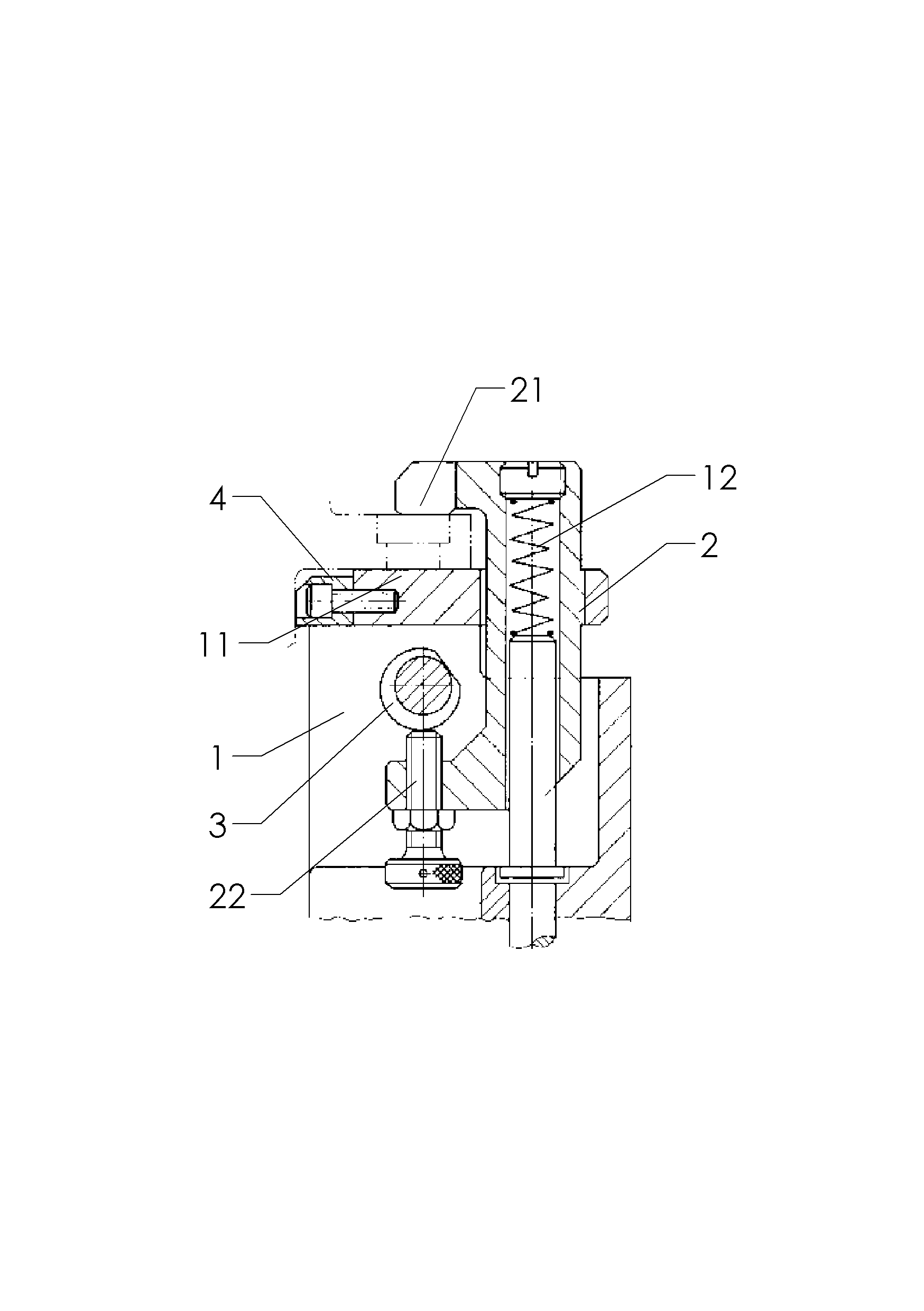
[0010] like figure 1 As shown: the cam pressing fixture in this implementation includes a fixed support part 1 and a movable pressing part 2, the supporting surface 11 of the fixed supporting part 1 cooperates with the lower surface of the boss on the workpiece, and the movable pressing part 2 is a hollow C Glyph, the fixed support part 1 is provided with a guide rod, the movable pressing part 2 is slidingly socketed with the guide rod, and the movable pressing part 2 is also provided with a compression spring 12 connected with the guide rod.

[0011] The C-shaped upper end 21 of the movable pressing part 2 cooperates with the upper surface of the workpiece boss, and a rotatable cam 3 is provided directly below the supporting surface 11 of the fixed supporting part 1, and the end of the C-shaped lower part of the movable pressing part 2 The head is a vertical adjustment bolt 22, and the vertical adjustment bolt 22 is connected with the movable pressing part 2 by threads.

[0...


PUM


Abstract

The invention discloses a cam compression clamp and aims to solve the problem that a boss horizontally extending out on a workpiece cannot be well fixed in the prior art. According to the scheme disclosed by the invention, the cam compression clamp comprises an engine bed, a fixed supporting part, a clamping jaw, a cam and a guide rod, wherein the fixed supporting part is used for lifting up the workpiece; the clamping jaw is used for compressing the upper surface of the workpiece; the cam is located below the clamping jaw and serves as a force application device; the guide rod is connected onto the clamp body; the clamping jaw has a freedom of vertical motion under the restraint of the guide rod; a reset spring is also arranged between the clamping jaw and the guide rod; the clamping jaw comprises an upper driven end and a lower driving end, wherein the upper driven end plays a clamping role, and the lower driving end plays a force application role. The cam compression clamp is characterized in that the cam is abutted with the lower driving end, and the geometric center of a clamping part of the upper driven end and the geometric center of the part, contacted with the cam, of the lower driving end are located on the same plumb line. The technical scheme disclosed by the invention has the characteristic that the boss horizontally extending out on the workpiece can be well fixed.

Description

technical field [0001] The invention relates to a clamp. Background technique [0002] Machine tool fixtures are indispensable and important process equipment in the machinery manufacturing industry, which can ensure the quality of machining, improve production efficiency, reduce production costs, and reduce labor intensity. [0003] In the actual processing process, the shape and structure of the workpiece are ever-changing. It is a long-term task for workers in the mechanical field to design corresponding fixtures for workpieces with different structures. The clamping of the horizontal boss on the workpiece is one of them. Contents of the invention [0004] The present invention intends to provide a cam pressing fixture to solve the problem of fixing the horizontally protruding boss on the workpiece in the prior art. [0005] The cam pressing fixture in this scheme includes a machine base, a fixed support part for holding up the workpiece, a jaw for pressing the upper ...

Claims


Application Information

Patent Timeline
IPC IPC(8): B23Q3/00
Inventor 袁晴波
Owner 重庆市南川区富民科技推广中心
Why Eureka
Try Eureka