
Device provided with stress monitoring equipment

A technology for monitoring equipment and installing stress, which is applied in the field of installing stress monitoring equipment, can solve problems such as increased loss of monitoring equipment, wrong stability judgments, and increased construction costs, so as to improve applicability, work efficiency, and accuracy , High installation efficiency

Inactive Publication Date: 2013-04-03
QINGDAO TECHNOLOGICAL UNIVERSITY
View PDF9 Cites 10 Cited by
  • Summary
  • Abstract
  • Description
  • Claims
  • Application Information

AI Technical Summary

Problems solved by technology

The purpose of real-time monitoring is to grasp the stress or other state changes in a certain direction of the surrounding rock or dam body engineering, and inaccurate monitoring data will give wrong guidance to the stability judgment of the subsequent project and increase safety hazards for the construction; during the installation process , unreasonable methods will increase the loss of monitoring equipment and increase construction costs; with the development of domestic and foreign economies, there are more and more large-scale projects and mines are getting deeper and deeper. In order to grasp the stability of the construction environment in real time to ensure production Safety, the requirement for engineering monitoring accuracy is getting higher and higher, so it is sought to design a detachable and reusable installation tool, especially a device for installing stress monitoring equipment. After ensuring that the monitoring equipment is installed reasonably and accurately, Can be disassembled and recycled many times, with good practical benefits and economic value

Method used


Image

  • Device provided with stress monitoring equipment
  • Device provided with stress monitoring equipment
  • Device provided with stress monitoring equipment

Examples


Embodiment

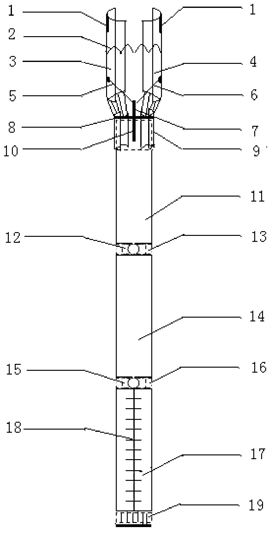
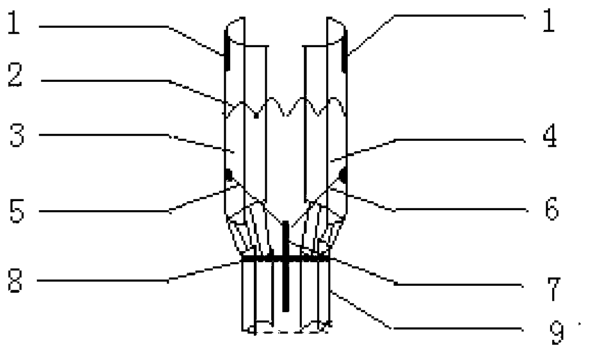
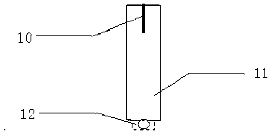
[0015] The main structure of this embodiment includes anti-friction gasket 1, elastic spring 2, left splint 3, right splint 4, skeleton left leg 5, skeleton right leg 6, skeleton bolt 7, chuck tail baffle 8, chuck tail cover Barrel 9, end mounting rod bolt 10, end mounting rod main body 11, end mounting rod lock 12, intermediate connecting rod front locking 13, intermediate connecting rod main body 14, intermediate connecting rod rear locking 15, tail mounting rod Lock buckle 16, tail mounting rod main body 17, tail mounting rod scale 18, tail mounting rod direction dial 19 and tail mounting rod direction hammer 20; two anti-friction gaskets 1 of symmetrical structure are respectively located on the left splint 3 and right splint 4 On the inside surface of the front section, the left splint 3 and the right splint 4 are symmetrical semi-arc structures, and the elastic spring 2 is fixedly connected between the left splint 3 and the right splint 4 to adjust the opening size of the...


PUM


Abstract

The invention belongs to the technical field of engineering constructions and relates to a device provided with stress monitoring equipment; the device comprises an anti-friction gasket, an elastic spring, a left splint, a right splint, a skeleton left leg, a skeleton right leg and a chuck unit, wherein the chuck unit comprises a skeleton bolt, a chuck tail baffle and a chuck tail sleeve; an end installation rod structure comprises an end installation rod bolt, an end installation rod body and an end installation rod lock catch, which are in a matching manner; a middle connection rod structure comprises a middle connection rod front lock catch, a middle connection rod body and a middle connection rod back lock catch, which are fixedly connected; and a tail installation rod structure comprises a tail installation rod lock catch, a tail installation rod body, tail installation rod scale, a tail installation rod direction dial plate and a tail installation rod direction dial hammer, which are connected in a matching manner. The technical process is simple, the positioning is accurate, the operation is convenient and simple, the structure adopted is simple, the theory is reliable, the manufacturing cost is low, the installation effect is good, and the installation efficiency is high.

Description

Technical field: [0001] The invention belongs to the technical field of engineering construction, and relates to a device for installing stress monitoring equipment, which is used for installing stress gauges and other stress monitoring equipment in underground engineering, slope engineering, and dam engineering. By using the improved positioning device, the Replaces the crude installation in the previous installation process. Background technique: [0002] At present, during or after the construction of underground engineering, slope engineering and dam engineering, in order to grasp the confining pressure or the stability of the dam body in real time and ensure the normal construction and use of the project, it is required to install monitoring equipment such as stress gauges in real time. Monitor the surrounding rock or the internal stress change of the dam body. The real-time monitoring situation will directly affect the follow-up safety assessment of the surrounding roc...

Claims


Application Information

Patent Timeline
Patent Type & Authority Applications(China)
IPC IPC(8): B25J1/00B25J19/00
Inventor 丛宇王在泉张黎明高速孙辉
Owner QINGDAO TECHNOLOGICAL UNIVERSITY
Learn More