Eureka AIR delivers breakthrough ideas for toughest innovation challenges, trusted by R&D personnel around the world.

A Vibration Optimization Method for Rail Transit Converter Based on Mode Decoupling Technology

A rail transit and optimization method technology, applied in design optimization/simulation, instrumentation, geometric CAD, etc., can solve problems affecting the fatigue life of converter modules, converter cabinet structural strength, vibration damping pad performance mismatch, damage, etc. problems, to achieve the effect of reducing the risk of mismatch, reducing the magnitude of vibration, and reducing failures in use

Active Publication Date: 2021-02-05
ZHUZHOU CSR TIMES ELECTRIC CO LTD
View PDF7 Cites 0 Cited by
  • Summary
  • Abstract
  • Description
  • Claims
  • Application Information

AI Technical Summary

Problems solved by technology

Due to the heavy weight of the transformer, and the alternating magnetostrictive force generated during the operation of the transformer will be transmitted to the converter cabinet, excessive vibration will seriously affect the fatigue life of the converter module, control box and other electrical components. Structural strength of the converter cabinet
[0003] At present, the fixing method of the transformer in the converter cabinet is relatively simple. It is directly fixed on the converter cabinet by bolts, or a vibration damping pad is installed between the transformer and the converter cabinet. There is still little research on parameters such as installation position and installation position, and the result is very likely to cause damage to the vibration damping pad due to mismatched performance

Method used


Image

  • A Vibration Optimization Method for Rail Transit Converter Based on Mode Decoupling Technology
  • A Vibration Optimization Method for Rail Transit Converter Based on Mode Decoupling Technology
  • A Vibration Optimization Method for Rail Transit Converter Based on Mode Decoupling Technology

Examples


Embodiment Construction

[0026] The present invention will be further described below in conjunction with the accompanying drawings and specific preferred embodiments, but the protection scope of the present invention is not limited thereby.

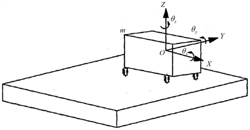
[0027] In practical applications, the transformer is the main vibration source in the converter cabinet. During the working process, the magnetostriction causes the transformer core to vibrate, and the vibration is transmitted to the converter cabinet and other components through the vibration damping pad, thus forming a pair of potential damage to pneumatic components. The kinetic energy caused by transformer vibration can be expressed as formula (2):

[0028]

[0029] In formula (2), T is the total kinetic energy of system vibration, is the system velocity column vector, for The transpose of , [M] is the system mass matrix.

[0030] At the i-th modal frequency, the total energy of the system is the sum of the energy obtained by vibration of all degre...


PUM


Abstract

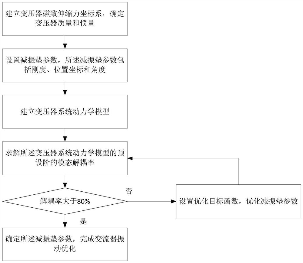
The invention discloses a vibration optimization method for a rail transit converter based on modal decoupling technology, comprising the following steps: S1. establishing a magnetostrictive force coordinate system of a transformer, and determining the mass and inertia of the transformer; S2. setting the parameters of a vibration damping pad , the damping pad parameters include stiffness, position coordinates and angles; S3. Establish a transformer system dynamics model; S4. Solve the modal decoupling rate of the preset order of the transformer system dynamics model; S5. When the When the modal decoupling rates are greater than the preset decoupling standard, determine the parameters of the vibration damping pad to complete the vibration optimization of the converter; otherwise, set an optimization objective function to optimize the parameters of the vibration damping pad, and then go to step S4. The invention has the advantages of quickly and accurately determining the setting scheme of the vibration damping pad of the converter, reducing the risk of mismatching between the vibration damping pad and the system, and the like.

Description

technical field [0001] The invention relates to the field of vibration optimization of rail traffic converters, in particular to a vibration optimization method for rail traffic converters based on modal decoupling technology. Background technique [0002] The existing converters for rail transit vehicles are usually composed of electrical components such as converter modules, control boxes, and transformers. Due to the heavy weight of the transformer, and the alternating magnetostrictive force generated during the operation of the transformer will be transmitted to the converter cabinet, excessive vibration will seriously affect the fatigue life of the converter module, control box and other electrical components. The structural strength of the converter cabinet. [0003] At present, the fixing method of the transformer in the converter cabinet is relatively simple. It is directly fixed on the converter cabinet by bolts, or a vibration damping pad is installed between the ...

Claims


Application Information

Patent Timeline
Patent Type & Authority Patents(China)
IPC IPC(8): G06F30/17G06F30/20G06F119/14
CPCG06F30/17G06F30/20
Inventor 曾亚平丁杰王永胜夏亮臧晓斌刘海涛李振鹏赵清良
Owner ZHUZHOU CSR TIMES ELECTRIC CO LTD
Why Eureka
Eureka Blog
Learn More