Bidirectional sealing butterfly valve

A two-way sealing, butterfly valve technology, applied in the direction of lift valve, valve device, engine components, etc., can solve problems such as leakage of sealing pair, and achieve the effect of saving man-hours, simple assembly process, and material saving

Active Publication Date: 2013-04-03
NAISEN VALVE IND
View PDF8 Cites 3 Cited by
  • Summary
  • Abstract
  • Description
  • Claims
  • Application Information

AI Technical Summary

Problems solved by technology

The valve seat is located on the valve body, and the section of the valve seat is trapezoidal. The biggest disadvantage of this structure is: when the medium flows in from the inlet side of the valve body, under the action of the medium, the sealing ring sticks to the valve seat to achieve sealing; When the medium flows in the reverse direction, the force of the medium makes the sealing ring tend to leave the valve seat, and there is no necessary specific pressure required for sealing between the sealing ring and the valve seat, and leakage occurs between the sealing pairs. Therefore, ordinary sealing butterfly valves only Suitable for one-way sealing conditions

Method used


Image

  • Bidirectional sealing butterfly valve
  • Bidirectional sealing butterfly valve
  • Bidirectional sealing butterfly valve

Examples


Embodiment

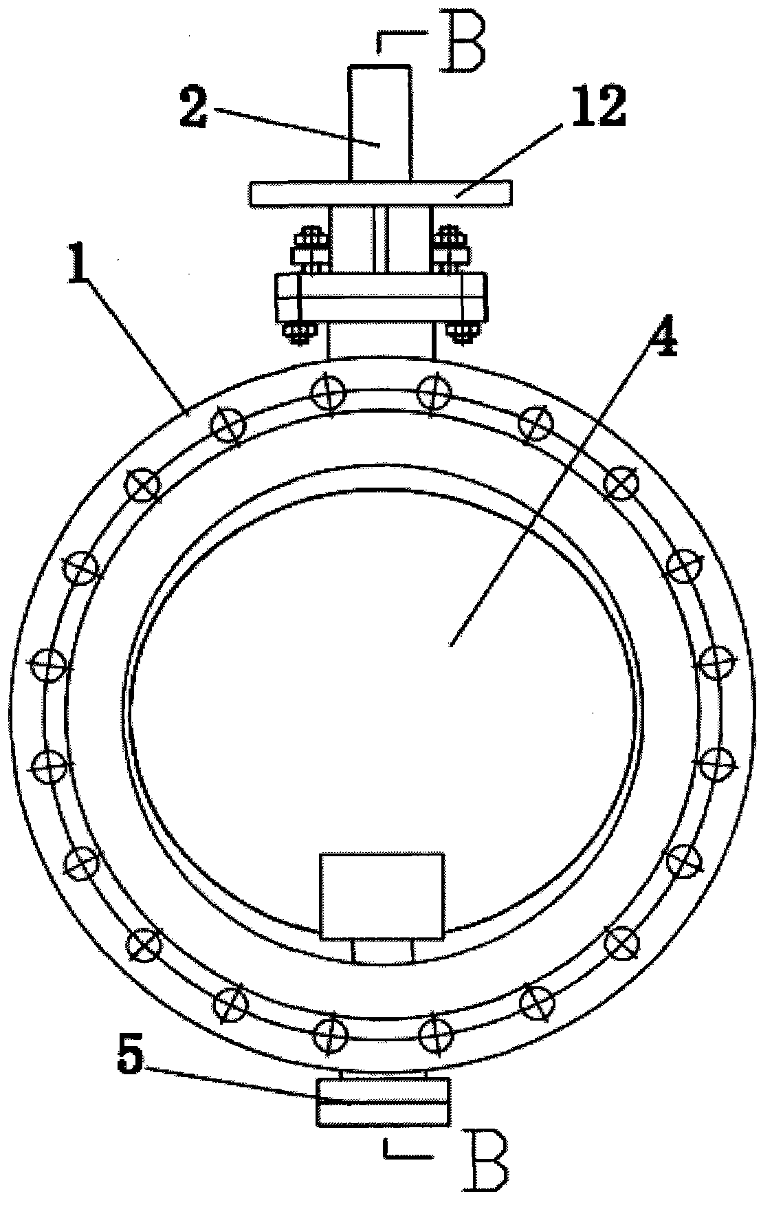
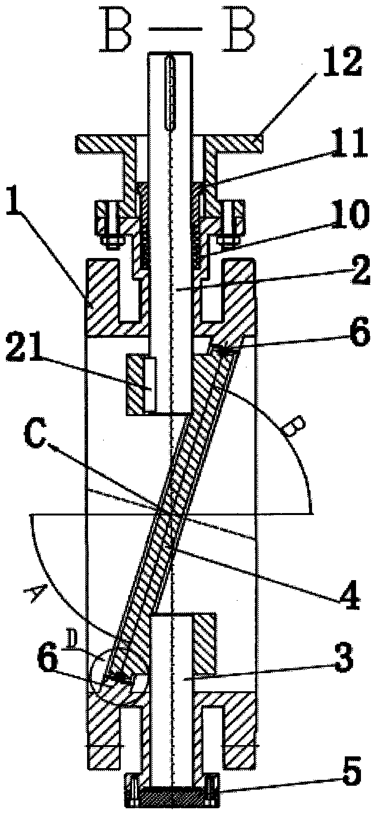
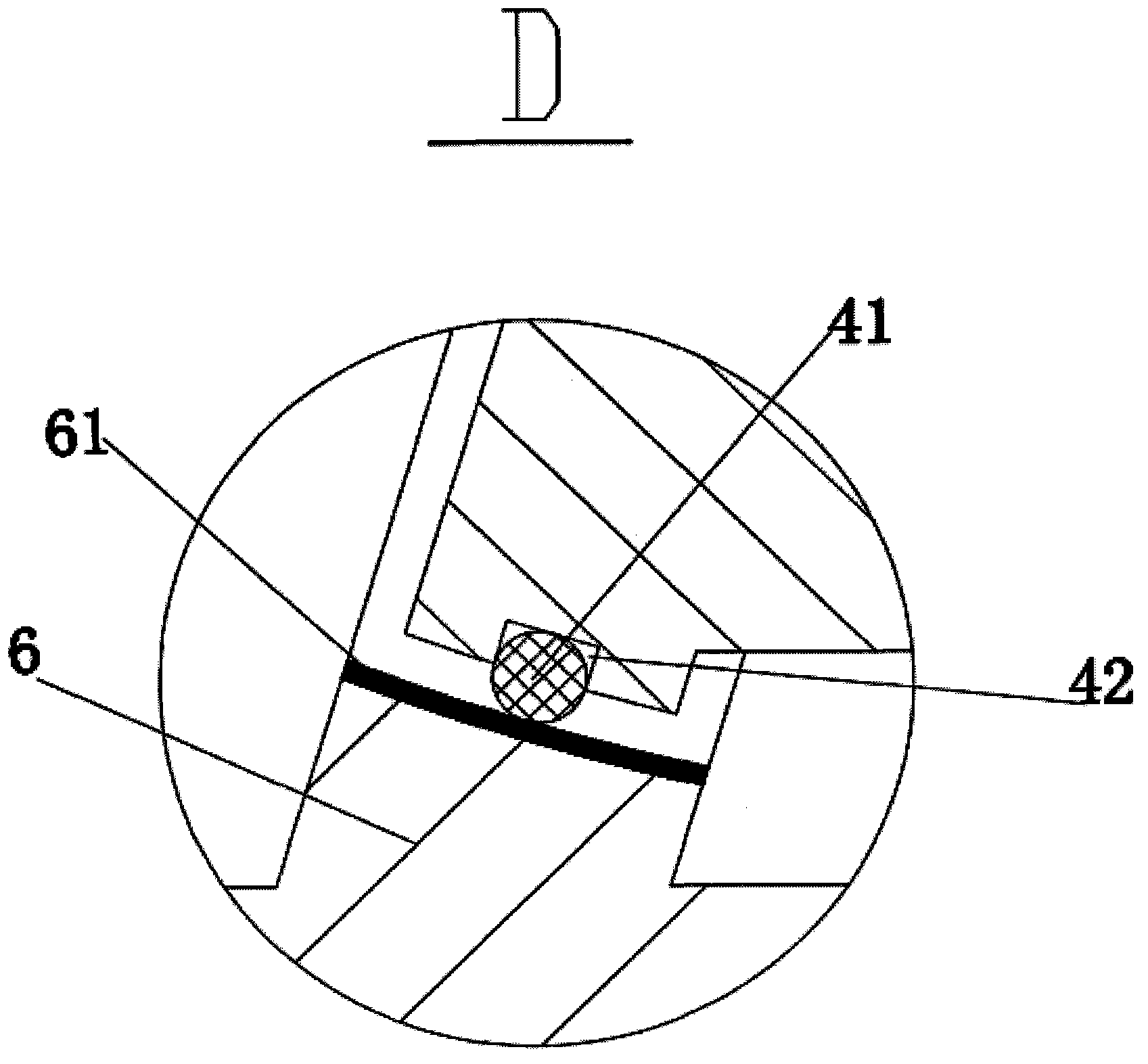
[0023] Such as figure 1 , figure 2 , image 3 As shown, the two-way sealing butterfly valve provided in this embodiment includes a valve body 1, a bracket 12 threadedly connected to the valve body 1, upper and lower valve stems 2, 3 in the valve body, a valve seat 6 in the valve body, and The butterfly plate 4 and the end cap 5 in the valve body. One end of the upper stem 2 is placed outside the valve body, and the other end is connected with the butterfly plate 4 placed in the valve body. A packing 10 is installed between the upper stem 2 and the valve body 1. The upper end is provided with a packing gland 11 to achieve a better sealing effect. One end of the lower valve stem 3 is matched and fixed with the end cover 5, and the other end of the lower valve stem is connected and fixed with the butterfly plate 4 through the key 21. The connection between the valve stem 2 and the butterfly plate 4 is a key 21 connection. The upper and lower valve stems and the butterfly plate 4 a...


PUM


Abstract

The invention discloses a bidirectional sealing butterfly valve, which comprises a valve body, an upper valve rod and a lower valve rod in the valve body, a valve seat positioned in the valve body, and a butterfly plate and an end cover which are arranged in the valve body, wherein one end of the upper valve rod is arranged outside the valve body, the other end of the upper valve rod is connected with the butterfly plate in the valve body, and one end of the lower valve rod is matched with the end cover to be fixed. The bidirectional sealing butterfly valve is characterized in that the other end of the lower valve rod is connected and fixed with the butterfly plate through a key, the valve seat is arranged at the upper side and the lower side in the valve body in an inclined mode, an upper periphery end surface of the valve seat is a valve seat sealing surface, an outer end surface of the butterfly plate is in clearance fit with the inclined valve seat sealing surface, a periphery ring surface of the butterfly plate is processed into an annular groove structure, a sealing piece is arranged in the annular groove structure, and the sealing piece and the inclined valve seat are in line contact. The bidirectional sealing butterfly valve disclosed by the invention has a small number of valve parts and is simple in assembly process, and working hours and material are saved; the valve can be sealed bidirectionally and reliably with zero leakage; and the valve has a lower opening-closing torque and long service life.

Description

Technical field [0001] The invention relates to a butterfly valve, particularly a two-way sealing butterfly valve. Background technique [0002] Ordinary sealed butterfly valve is composed of valve body, butterfly plate, pressure ring, sealing ring, valve stem, bolts and other parts. This structure increases the thickness of the butterfly valve, causes the flow resistance of the butterfly plate to increase, and reduces the flow capacity of the valve. Cause unnecessary energy waste. [0003] Ordinary butterfly valve sealing ring is fixed on the butterfly plate by pressure ring and bolts. The valve seat is located on the valve body, and the cross section of the valve seat is a trapezoid. The biggest drawback of this type of body is: when the medium flows in from the inlet side of the valve body, under the action of the medium, the sealing ring closes to the valve seat to achieve sealing; When the medium flows in the reverse direction, the sealing ring tends to leave the valve seat,...

Claims


Application Information

Patent Timeline
IPC IPC(8): F16K1/226F16K1/36F16K1/48F16K1/42
Inventor 缪震华董侠秀程伟
Owner NAISEN VALVE IND
Why Eureka
Try Eureka