Pressure-adaptive continuous drainer for gas conveying pipeline

A transmission pipeline, self-adaptive technology, applied in the pipeline system, gas/liquid distribution and storage, mechanical equipment, etc., can solve the problems that do not meet the requirements of energy saving and environmental protection, and achieve the effect of large pressure bearing capacity and wide application range

Active Publication Date: 2014-07-23
HUNAN SHIYIWEI VALVE MFG CO LTD
View PDF7 Cites 0 Cited by
  • Summary
  • Abstract
  • Description
  • Claims
  • Application Information

AI Technical Summary

Problems solved by technology

[0003]①Low applicable pressure and small overload capacity
When the medium pressure in the pipeline fluctuates too much, the drainer is easy to be broken down
[0004]②The internal pipes and partitions of traditional drains are completely enclosed in the cylinder. Can be scrapped but not repaired (that is, poor repairability), especially for drains with a large number of partitions, it is impossible to inspect or deal with pipe perforation accidents at all
[0005]③ Due to the small fouling area and frequent dredging, increased (large) maintenance workload
[0006]④Requires frequent replenishment of water, which does not meet the requirements of energy conservation and environmental protection

Method used


Image

  • Pressure-adaptive continuous drainer for gas conveying pipeline
  • Pressure-adaptive continuous drainer for gas conveying pipeline
  • Pressure-adaptive continuous drainer for gas conveying pipeline

Examples


Embodiment Construction

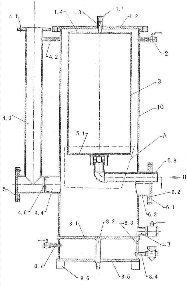
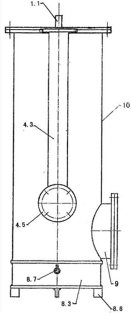
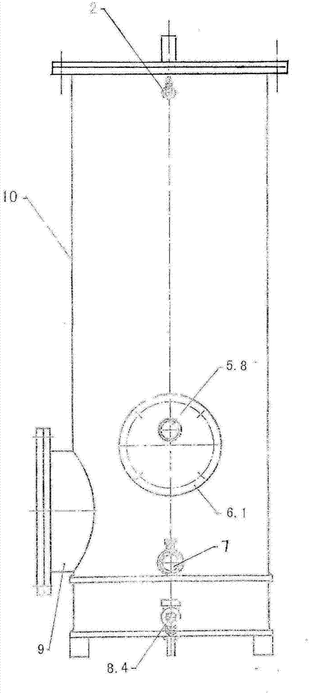
[0022] The specific implementation manners of the present invention will be further described in detail below in conjunction with the accompanying drawings.

[0023] (Such as figure 1 As shown), a pressure-adaptive gas delivery pipeline continuous drainer includes a drainer upper cover assembly, a fault diagnosis valve 2, a drainer buoy assembly, a drainer inlet pipe assembly, a sealing body assembly, a movable drain pipe assembly, Sewage pipe 7, steam heating chamber assembly, inspection hole (assembly) 9 and main cylinder body 10, wherein the drainer upper cover assembly is composed of an upper guide sleeve 1.1, an upper cover plate 1.2 and a guide rod 1.3; the drainer buoy assembly is composed of a buoy body 3. The buoy upper end plate 1.4 and the buoy lower end plate 5.1 are formed. The buoy upper end plate 1.4 and the buoy lower end plate 5.1 are fixedly connected to the upper and lower ends of the buoy body 3 respectively to form a floating body. The shape of the fl...


PUM


Abstract

The invention discloses a pressure self-adaptive continuous drainer for gas conveying pipelines. A steam inlet pipe and a steam drainage pipe are installed on the side wall of an auxiliary cylinder body with an upper end plate and a lower end plate, and a sewage discharge pipe is arranged on the lower end wall of the main cylinder body. The wall of the main cylinder is connected with a bracket guide pipe, and the water outlet horizontal pipe passes through the bracket block and extends into the inner cavity of the main cylinder, and then connects with the drainage standpipe. Between them, the transition plate is fixedly connected to the lower side of the lower end plate of the buoy, and the guide rod at the center of the upper end plate of the buoy is in the upper guide sleeve at the center of the upper cover. The water inlet horizontal pipe is installed on the lower end side wall of the main cylinder, the lower end of the water inlet vertical pipe is connected with the water inlet horizontal pipe, and the upper end of the water inlet vertical pipe is connected with the gas delivery main pipe through the water inlet end flange. This drainer can automatically adapt to the pressure in the gas delivery pipeline, does not need to replenish water, and is easy to maintain.

Description

technical field [0001] The invention relates to a drainer, in particular to a pressure-adaptive continuous drainer for gas conveying pipelines used in industrial enterprises to remove condensed water in conveying pipelines such as gas, compressed air, steam, and natural gas. Background technique [0002] The pipeline used to transport gas will accumulate condensed water after a certain distance and time. In order to ensure the unimpeded delivery of gas and ensure the high efficiency and safety of use, the condensed water in the gas pipeline must be discharged, and the condensed water must be discharged (released) The equipment (or device) used is called a gas pipe drain. Before the present invention, those skilled in the art have designed or manufactured different types of drainers, such as ZL200420034909.0 "Automatic drainer without pollution and anti-gas leakage", ZL200620051238.8 "A new type of drainer for gas pipelines", ZL200720064040. 8 "Gas pipeline automatic drainer...

Claims


Application Information

Patent Timeline
Patent Type & Authority Patents(China)
IPC IPC(8): F17D3/14
Inventor 杨笛蔡牧
Owner HUNAN SHIYIWEI VALVE MFG CO LTD
Why Eureka
Try Eureka