Ceiling fixing fastener assembly for LED (Light Emitting Diode) lamp

A technology of LED lamps and fixing buckles, which is applied to the parts of lighting devices, lighting devices, light sources, etc., can solve the problems of inconvenient disassembly, etc., and achieve the effect of easy installation, quick disassembly, and quick installation

Active Publication Date: 2013-04-03
浙江捷莱光电科技有限公司
View PDF10 Cites 6 Cited by
  • Summary
  • Abstract
  • Description
  • Claims
  • Application Information

AI Technical Summary

Problems solved by technology

The utility model still uses the shrapnel, but the shrapnel is in a non-stressed state during installation. After installation, the downlight is fixed in the installation hole by buckling the second end of the fixing plate. The installation is very convenient, but It is still not convenient to realize disassembly during maintenance

Method used


Image

  • Ceiling fixing fastener assembly for LED (Light Emitting Diode) lamp
  • Ceiling fixing fastener assembly for LED (Light Emitting Diode) lamp
  • Ceiling fixing fastener assembly for LED (Light Emitting Diode) lamp

Examples


Embodiment 1

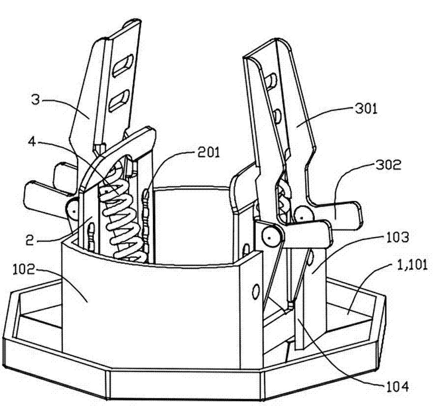
[0025] see figure 1 and Figure 8 , a ceiling fixing buckle assembly for an LED lamp, comprising a decorative cover 1, a fixing plate 2 arranged on the decorative cover 1, a fixing buckle 3 pivotally connected to the fixing plate 2, and the fixing buckle 3 in the installation position and the locking position Overturned elastic element 4. In this embodiment, the elastic element 4 is a tension spring.

[0026] The decorative cover 1 is provided with a face ring 101 that can cover the ceiling 5 mounting holes and a wall ring 102 that stretches into the ceiling 5 mounting holes. The two opposite sides of the wall ring 102 are provided with flat installation parts 103. A mounting groove 104 is provided in the middle.

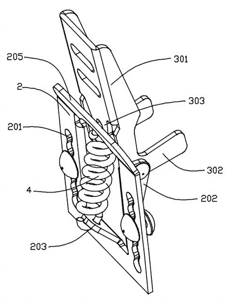
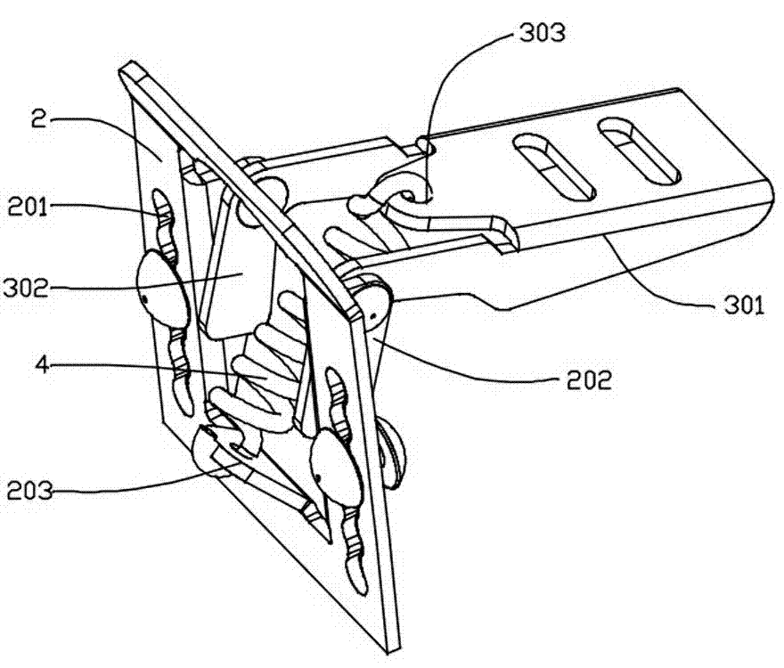
[0027] see figure 2 and image 3 In the middle of the fixed plate 2, there is an overturning groove 204, on both sides of the overturning groove 204 there are two pivotal support plates 202 extending outward, and on the fixed plate 2 on both sides of the pivot...

Embodiment 2

[0035] In this embodiment, the elastic element 4 is a compression spring, so except that the elastic element 4 and the installation structure of the elastic element 4 are slightly different, the others are the same as the first embodiment.

[0036] see Figure 5 , in this embodiment, since the elastic element 4 is a compression spring, in order to turn over the fixing buckle 3, the upper fixing tongue 303 on the fixing buckle 3 extends to the opposite side of the buckling part 301 of the fixing buckle 3 on the pivot axis. end. For the settings of the first flip angle α1 and the second flip angle α2, see Figure 7 .

[0037]

Embodiment 3

[0039] In this embodiment, the elastic element 4 is a torsion spring, so except that the elastic element 4 and the installation structure of the elastic element 4 are slightly different, the others are the same as the first embodiment.

[0040] see Figure 6 , in this embodiment, the torsion spring is installed on the upper part of the back side of the fixed plate opposite to the pivotal support plate 202 through a pin shaft. The upper fixing tongue 303 on the fixing buckle 3 is substantially the same as that in the second embodiment, and is also located at the other end of the crimping portion relative to the pivot axis of the fixing buckle. The settings of the first flip angle α1 and the second flip angle α2 also refer to Figure 7 .


PUM


Abstract

The invention discloses a ceiling fixing fastener assembly for an LED (Light Emitting Diode) lamp. The ceiling fixing fastener assembly comprises a decorative cover and a fixing fastener, wherein the decorative cover at least comprises two circumferentially and uniformly distributed mounting parts, and the fixing fastener is hinged on the mounting part and is provided with a fastening part and an elastic element; the installation of the elastic element comprises the following steps that the direction of acting force acting on the fixing fastener reverses after turning a first turnover angle, so that the fixing fastener turns over from a mounting position to a locking position; and the direction of acting force acting on the fixing fastener reverses after turning a second turnover angle, so that the fixing fastener turns over from a locking position to a mounting position; and the first turnover angle and the second turnover angle are acute angles. After the fixing fastener rotates over the turnover angle, the acting force of the elastic element on the fixing fastener reverses to generate turnover, so that the LED lamp can be quickly fixed and dismantled on the ceiling by the fixing fastener without damaging a mounting surface, and the mounting reliability of the LED lamp is improved.

Description

technical field [0001] The invention relates to an LED lighting fixture, in particular to a ceiling fixing buckle assembly of the LED lighting fixture. Background technique [0002] For existing ceiling-mounted LED lamps, including downlights, spotlights, etc., the fixing buckle assembly generally adopts a snap spring structure. Such as a kind of LED downlight disclosed by the Chinese utility model patent whose notification number is CN201836776U. The LED downlight includes a decorative ring and a bracket for fixing the LED light. The decorative ring is in the shape of a circular tube, the lower opening of the decorative ring has a circle of flanging turned outwards, and a pair of snap rings are arranged on the outer wall of the decorative ring. There is also a shrapnel structure, such as the LED downlight outer ring disclosed in the Chinese utility model patent CN201836776U. The outer ring of the LED downlight includes an outer ring set on the body of the LED lamp. The o...

Claims


Application Information

Patent Timeline
Patent Type & Authority Applications(China)
IPC IPC(8): F21V21/03F21Y101/02
Inventor 戴军历
Owner 浙江捷莱光电科技有限公司
Why Eureka
Try Eureka