Fatigue testing machine

A fatigue testing machine and stand technology, applied in the field of fatigue testing machines, can solve problems such as unfavorable testing equipment, increased power consumption, and increased testing costs, and achieve the effects of shortening testing time, reducing power consumption, and simplifying fatigue testing.

Active Publication Date: 2013-04-03
合肥微研机电技术有限公司
View PDF7 Cites 13 Cited by
  • Summary
  • Abstract
  • Description
  • Claims
  • Application Information

AI Technical Summary

Problems solved by technology

[0002] The service life of mechanical parts is one of the main performance requirements of mechanical equipment, especially the life test of a single part, sometimes it takes too long, and some use the accelerated life test method, but the test equipment itself has some new mechanical properties Requirements, such as increasing the speed of the test machine or increasing the force of the test, which is not good for the test equipment itself, but also increases the power consumption of the operation and increases the cost of the test. The suction and exhaust of the refrigeration compressor In the valve life fatigue test, since the service life of the compressor is required to be more than 10 years, for this requirement, the general cam mechanism cannot be used in the fatigue test. For the test of the suction valve used in the multi-cylinder compressor, the The life fa

Method used


Image

  • Fatigue testing machine
  • Fatigue testing machine
  • Fatigue testing machine

Examples


Embodiment Construction

[0024] In order to make the object, technical solution and advantages of the present invention clearer, the present invention will be further described in detail below in conjunction with the accompanying drawings and embodiments. It should be understood that the specific embodiments described here are only used to explain the present invention, not to limit the present invention.

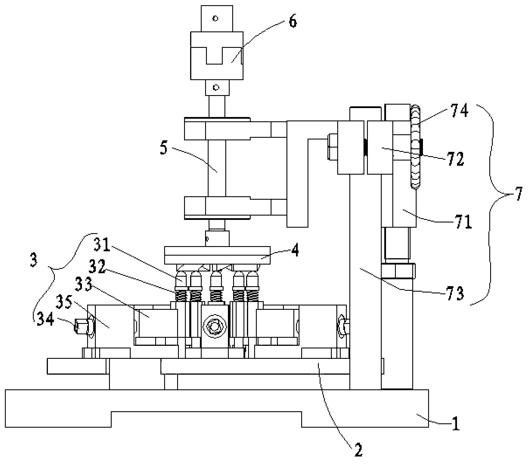
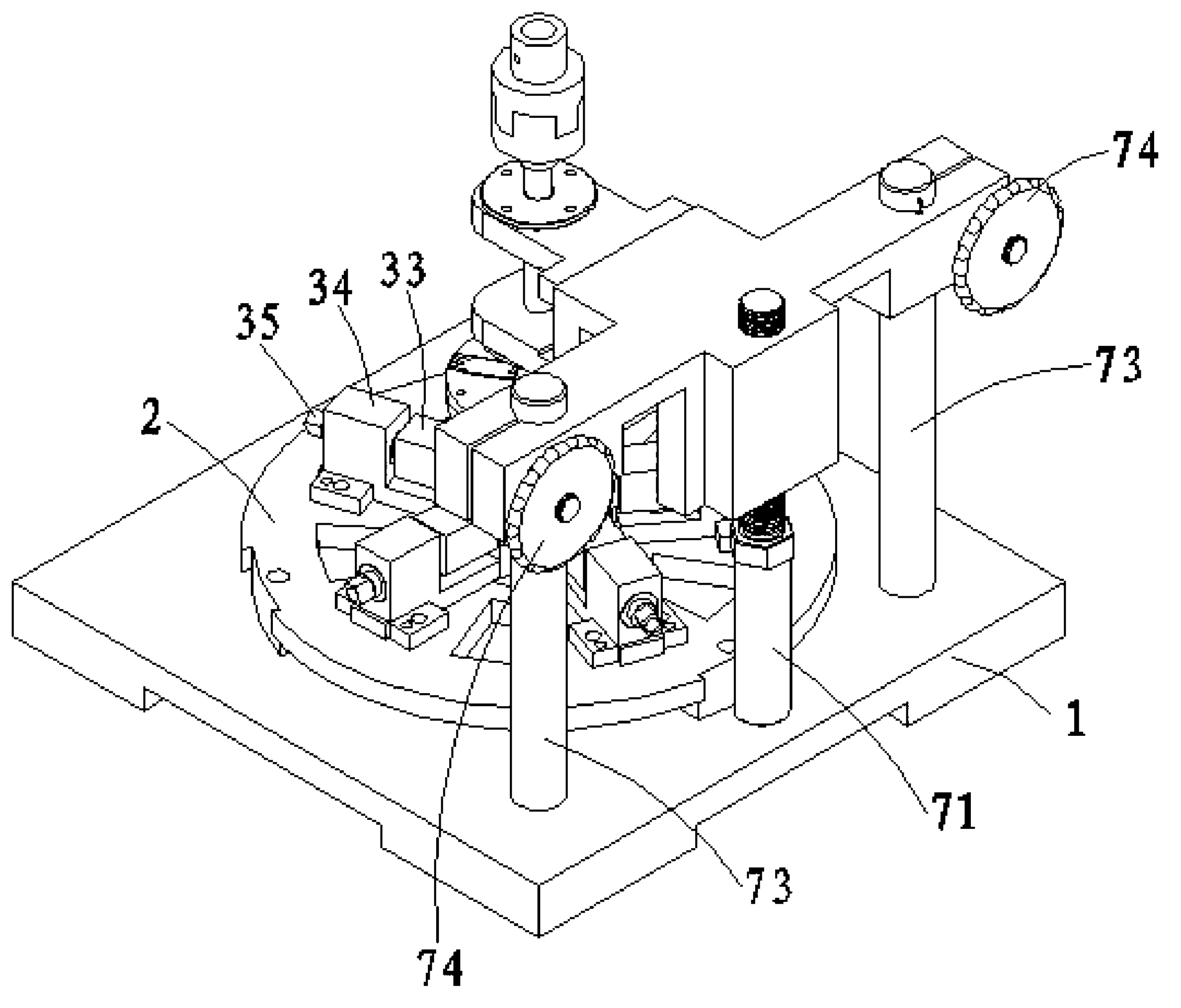
[0025] Please also refer to figure 1 , figure 2 in, figure 1 It is a schematic diagram of the overall structure of the fatigue testing machine of the present invention, figure 2 It is a perspective view of the overall structure of the fatigue testing machine of the present invention. Such as figure 1 , 2 As shown in , a fatigue testing machine of the present invention includes a machine base 1 , a valve plate fixing mechanism 2 , a punching mechanism 3 , a punch driving mechanism and a driving mechanism adjusting device 7 .

[0026] All components of the fatigue testing machine are installe...


PUM


Abstract

The invention relates to a fatigue testing machine which comprises a machine base, a valve sheet fixing mechanism, a punching mechanism, a punch driving mechanism and a driving mechanism regulating device, wherein the valve sheet fixing mechanism is arranged on the machine base and is used for fixing a valve sheet; the punching mechanism comprises a punch which has elasticity recovery and is used for exerting pressure on the tongue of the valve sheet by the bottom end; the number of the punch corresponds to the number of the tongue on the valve sheet which is arranged on the valve sheet fixing mechanism; the punch driving mechanism comprises a power device, a driving shaft and a driving wheel; the driving shaft is driven to rotate by the power device; the driving wheel is fixedly connected at the bottom end of the driving shaft; a plurality of cams are arranged on the bottom end of the driving wheel; and the bottom ends of the cams are lower than the top end of the punch. The fatigue testing machine disclosed by the invention has the advantages that the fatigue test on the service lives of the air suction and exhaust valve sheets of a refrigeration compressor is simple and convenient, the test duration is greatly shortened, experiment cost is reduced, and meanwhile development cycle of a new product is shortened and power consumption is reduced.

Description

technical field [0001] The invention relates to a testing machine, in particular to a fatigue testing machine applied to the fatigue testing of valve plates. Background technique [0002] The service life of mechanical parts is one of the main performance requirements of mechanical equipment, especially the life test of a single part, sometimes it takes too long, and some use the accelerated life test method, but the test equipment itself has some new mechanical properties Requirements, such as increasing the speed of the test machine or increasing the force of the test, which is not good for the test equipment itself, but also increases the power consumption of the operation and increases the cost of the test. The suction and exhaust of the refrigeration compressor In the valve life fatigue test, since the service life of the compressor is required to be more than 10 years, for this requirement, the general cam mechanism cannot be used in the fatigue test. For the test of t...

Claims


Application Information

Patent Timeline
IPC IPC(8): G01M13/00
Inventor 梅先松
Owner 合肥微研机电技术有限公司
Why Eureka
Try Eureka