Multi-layer shearing direct shear device

A shearing instrument, a direct technology, applied in the direction of applying stable shearing force to test the strength of materials, etc., can solve the problems of high cost of purchasing instruments, high manpower, time and financial resources, and large size disparity of bulk coarse grain materials. Achieve the effect of improving reliability and accuracy and saving manpower

Active Publication Date: 2013-04-03
昆明理工大学设计研究院有限公司
View PDF5 Cites 9 Cited by
  • Summary
  • Abstract
  • Description
  • Claims
  • Application Information

AI Technical Summary

Problems solved by technology

Even if the 4-5 soil samples are completely consistent, the structure of the soil samples in the shear plane during the sample loading process is completely different due to the large disparity in the particle size of the bulk coarse-grained material and the randomness of the particle size distribution. , so the experimental bulk shear strength parameter error is large
At the same time, a sample is only subjected to one shear test, which wastes a lot of financial, materi

Method used


Image

  • Multi-layer shearing direct shear device
  • Multi-layer shearing direct shear device
  • Multi-layer shearing direct shear device

Examples


Embodiment 1

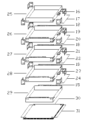
[0037] Embodiment 1: the direct shearer device of the multi-layer shearing of the present embodiment, comprises outer frame device 54, shearing box device 55, horizontal loading device 58 and support device 56, shearing box device 55 and horizontal loading device 58 are distributed inside the outer frame device 54, and the supporting device 56 is positioned at the side of the shear box device 55; the position corresponding to the shear box device 55 on the top of the outer frame device 54 is provided with a vertical loading device, and the position corresponding to the horizontal loading device 58 is provided with a Lifting device 57; The multi-layer steel frame that supports horizontal loading device 58 is arranged on the outer frame device 54, and shear box device 55 has multi-layer shear box, and supporting device 56 has multi-layer support block, multi-layer steel frame, multi-layer The layer shear box is flush with each layer corresponding to the multi-layer support block....

Embodiment 2

[0038] Embodiment 2: the direct shearer device of the multi-layer shearing of the present embodiment, the outer frame device 54, the shear box device 55, the horizontal loading device 58 and the supporting device 56, the shear box device 55 and the horizontal loading device 58 Distributed inside the outer frame device 54, the supporting device 56 is located on the side of the shear box device 55; the top of the outer frame device 54 is provided with a vertical loading device at the position corresponding to the shear box device 55, and a hoisting device at the position corresponding to the horizontal loading device 58 Device 57; the multi-layer steel frame supporting horizontal loading device 58 is arranged on the outer frame device 54, and the shear box device 55 has five layers of shear boxes, and the supporting device 56 has five layers of supporting blocks, five layers of steel frame, five layers of Each layer corresponding to the shear box and the five layers of supporting...


PUM


Abstract

The invention provides a multi-layer shearing direct shear device and belongs to the technical field of worker supplies. The multi-layer shearing direct shear device comprises an outer framework device, a shear box device, a horizontal loading device and a carrying device, wherein the shear box device and the horizontal loading device are distributed in the outer framework device; the carrying device is positioned on the side edge of the shear box device; at the top of the outer framework device, a vertical loading device corresponds to the shear box device and a hanging device corresponds to the horizontal loading device; a plurality of layers of steel frames for supporting the horizontal loading device are arranged on the outer framework device; the shear box device is provided with a plurality of layers of shear boxes; the carrying device is provided with a plurality of layers of bearing blocks; and a plurality of layers of steel frames, a plurality of layers of shear boxes and a plurality of layers of bearing blocks are flush with each other layer by layer. By the multi-layer shearing direct shear device, direct shear test on a plurality of shear surfaces of the same soil sample can be realized.

Description

technical field [0001] The invention provides a direct shear device for multi-layer shearing, which belongs to the technical field of agricultural and industrial supplies. Background technique [0002] The formation of dumps is an inevitable result of mining, especially open pit mining. Its constituent materials are mainly composed of topsoil and rocks stripped and covered during open-pit mining, and sometimes include off-surface ore and lean ore that may be recovered. Because the dump site is a huge artificial loose accumulation body, this characteristic makes the dump site very easy to form mine geological disasters such as landslides and mud-rock flows. Therefore, the accurate determination of the mechanical parameters of rock and soil materials is the key factor for evaluating and controlling the instability of geotechnical engineering, and its significance in geotechnical engineering is self-evident. However, due to the inhomogeneity and randomness of the particle...

Claims


Application Information

Patent Timeline
IPC IPC(8): G01N3/24
Inventor 王光进孔祥云杨春和张超
Owner 昆明理工大学设计研究院有限公司
Why Eureka
Try Eureka