Computing method of path changing and device thereof

A path calculation and path technology, applied in calculation, data processing application, prediction, etc., can solve the problem of single content and achieve the effect of improving user experience

Inactive Publication Date: 2013-04-03
CENNAVI TECH
View PDF4 Cites 13 Cited by
  • Summary
  • Abstract
  • Description
  • Claims
  • Application Information

AI Technical Summary

Problems solved by technology

[0004] Provide a method and device for calculating a transfer route, which can solve the problem that the content provided b

Method used


Image

  • Computing method of path changing and device thereof
  • Computing method of path changing and device thereof
  • Computing method of path changing and device thereof

Examples


Embodiment 1

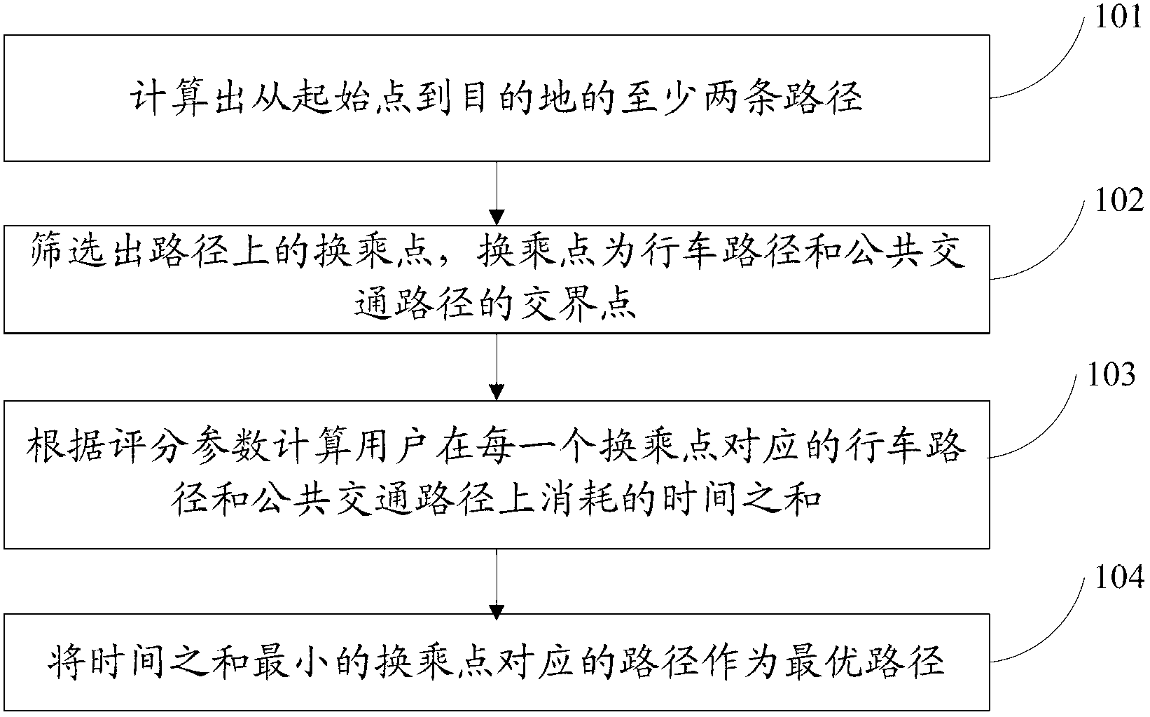
[0077] This embodiment provides a method for calculating a transfer route, such as figure 1 As shown, the method includes:

[0078] 101. Calculate at least two paths from the starting point to the destination.

[0079] 102. Filter out the transfer point on the route, and the transfer point is the junction point between the driving route and the public transport route.

[0080] Wherein, the route between the starting point and the transfer point is a driving route, and the route between the transfer point and the destination is a public transportation route.

[0081] Specifically, the filtering out transfer points on the route includes: obtaining all transfer points in the route buffer zone, wherein the buffer zone is an area within a set range centered on the route ;

[0082] Calculate the driving route and public transport route corresponding to each transfer point;

[0083] According to specific rules, transfer points that meet the rules are determined from all obtained ...

Embodiment 2

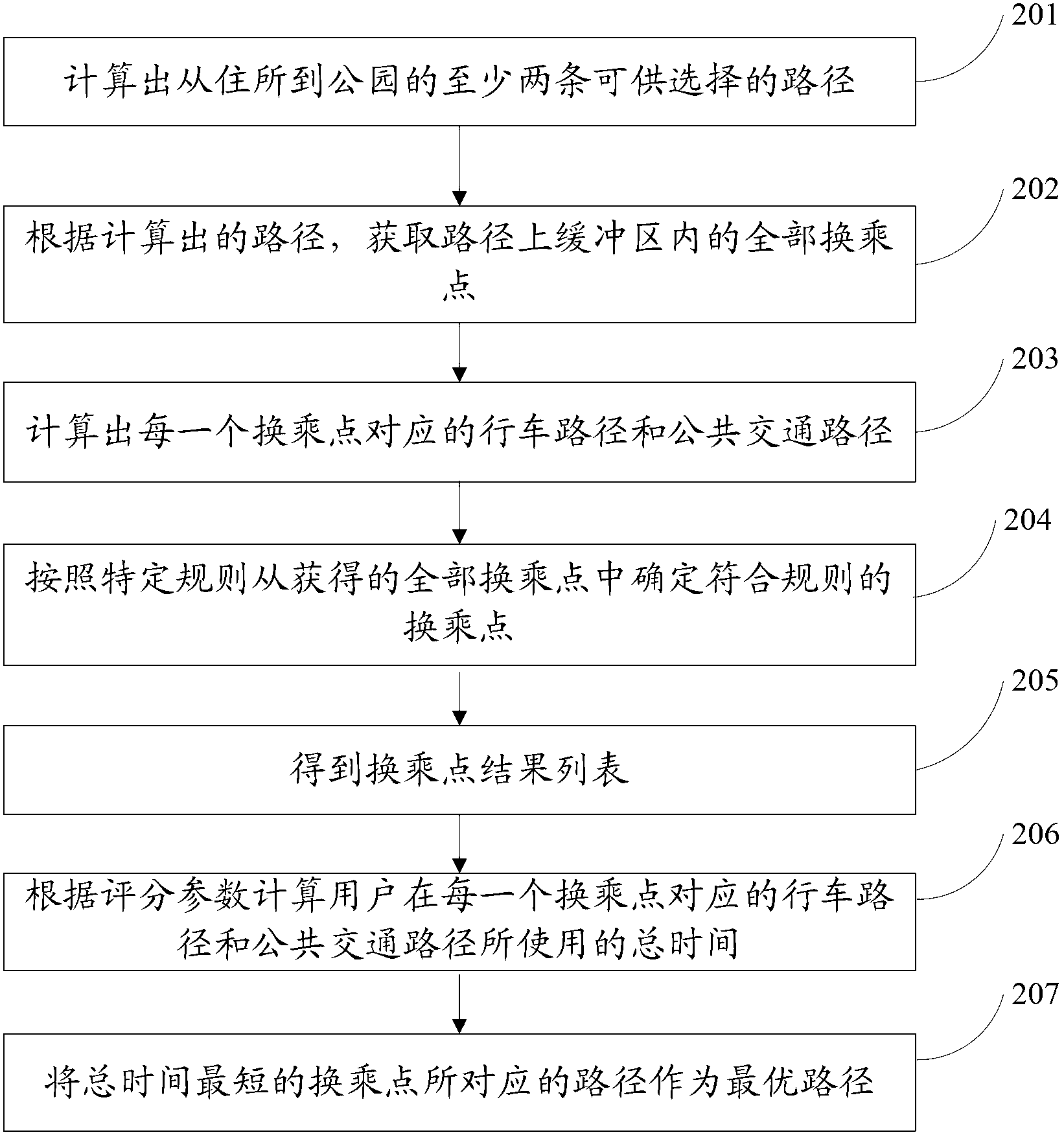
[0110] This embodiment provides a method for calculating a transfer route, providing a scenario where a user travels from his residence (starting point) to a park (destination) in the city center to play. In order to avoid congestion in the city center, the user drives from his residence to At a transfer point, change the subway to the park, such as figure 2 As shown, the method includes:

[0111] 201. Calculate at least two alternative paths from the residence to the park.

[0112] It should be noted that the route calculation method can refer to the current navigation route calculation method, which will not be described in detail here, and the route with subway stations should be given priority when calculating.

[0113] 202. Acquire all transfer points in the buffer zone on the route according to the calculated route.

[0114] For example, a road point is taken every several meters on the path, and an area can be obtained by taking these road points as the center and a ...

Embodiment 3

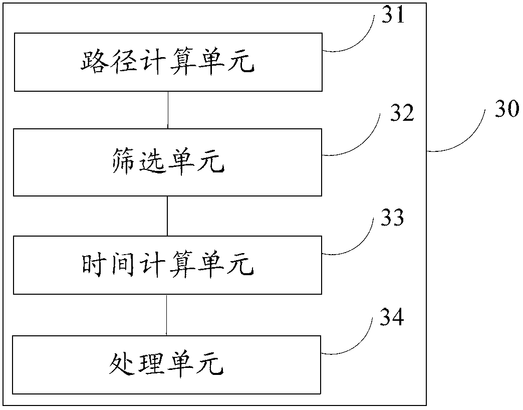
[0141] This embodiment provides a transfer route calculation device 30, such as image 3 As shown, the device 30 includes:

[0142] a path calculation unit 31, configured to calculate at least two paths from the starting point to the destination;

[0143] A screening unit 32, configured to screen out transfer points on the route, where the transfer points are junction points between driving routes and public transport routes;

[0144] The time calculation unit 33 is used to calculate the sum of the time spent by the user on the driving route and public transport route corresponding to each transfer point according to the scoring parameters;

[0145] The processing unit 34 is configured to use the route corresponding to the transfer point with the smallest time sum as the optimal route.


PUM


Abstract

The embodiment of the invention discloses a computing method of path changing and device thereof. The method comprises the steps of figuring out at least two paths from the start point to the destination; screening out the changing stops of the paths, the changing stops is the crossing point of driving paths and public transport paths; calculating the total time consumed in the driving paths and the public transport paths corresponding to each of the changing stops according to scoring parameters; and choosing the path corresponding to the changing stop with smallest total time as the best path. The computing method of the path changing applies to traffic navigation services.

Description

technical field [0001] The invention relates to the technical field of intelligent traffic information services, in particular to a transfer route calculation method and device. Background technique [0002] With the development of the modern automobile industry, a series of traffic problems have been caused: traffic congestion, road blockage, and frequent traffic accidents. These traffic problems have brought great inconvenience to people's daily travel, and have also caused huge economic losses to the society. In order to improve traffic conditions, Intelligent Transportation System (Intelligent Transportation System, English abbreviation ITS) came into being. Provide comprehensive traffic guidance services for people to travel through real-time and accurate traffic report, navigation planning and other services. [0003] There are at least the following problems in the prior art: the current navigation service only considers a single travel mode of the user, either a se...

Claims


Application Information

Patent Timeline
IPC IPC(8): G06Q10/04
Inventor 于洋戴希陈耀
Owner CENNAVI TECH
Why Eureka
Try Eureka