Lateral-bottom-fed coil loading machine with hydraulic rocker-slider mechanism

A rocker slider and hydraulic technology, applied in the direction of electrical components, circuits, cables/conductors, etc., can solve the problems of inability to synchronize displacement, increase difficulty, change, etc., and achieve the effect of improving work efficiency and simple and reliable structure

Active Publication Date: 2013-04-03
HEFEI SMARTER TECH GROUP CORP
View PDF8 Cites 4 Cited by
  • Summary
  • Abstract
  • Description
  • Claims
  • Application Information

AI Technical Summary

Problems solved by technology

[0004] In the prior art, there are two kinds of side and bottom loading machines, one is to use the worm gear screw screw mechanism, and use double hydraulic cylinders to directly push the wire reel rack to realize the upper and lower racks. Good, but the mechanical efficiency is very low, generally only 10-20%, due to the low auxiliary transmission, the mechanical wear of each part is very large
The other is to use double hydraulic cylinders to directly push the reel frame to realize the operation of the upper plate and the lower plate, but according to the Pascal principle of hydraulic transmission, the hydraulic oil will flow to the side with the smaller load, and the leakage of the hydraulic oil supply components will vary with the load. Therefore, in theory, displacement synchronization cannot be achieved.
And the amount of leakage will increase with the wear of moving parts. Related problems need to be solved by improving the manufacturing accuracy of the hydraulic cylinder and installing limit blocks on the guide rails. This form obviously greatly increases the difficulty of implementation, so it is not widely used

Method used


Image

  • Lateral-bottom-fed coil loading machine with hydraulic rocker-slider mechanism
  • Lateral-bottom-fed coil loading machine with hydraulic rocker-slider mechanism
  • Lateral-bottom-fed coil loading machine with hydraulic rocker-slider mechanism

Examples


Embodiment Construction

[0026] In this embodiment, the structure of the upper plate machine under the side of the hydraulic rocker slider is set as follows:

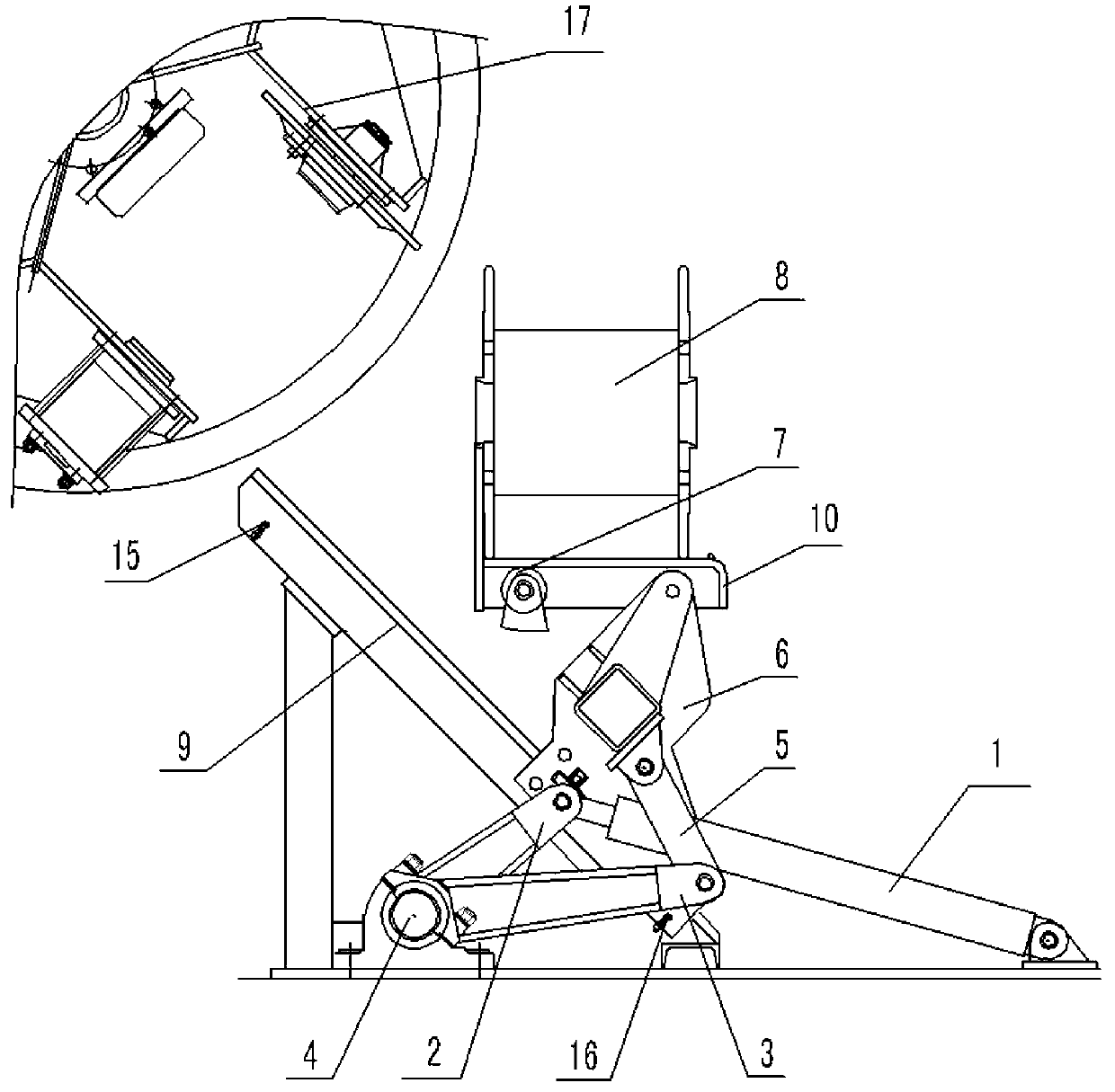
[0027] see figure 1 , the hydraulic cylinder 1 as the driving mechanism is hinged with the transmission rocker 2 with its piston rod end, and the other end of the transmission rocker 2 is fixedly sleeved on the main shaft 4 for driving the rotation of the main shaft 4.

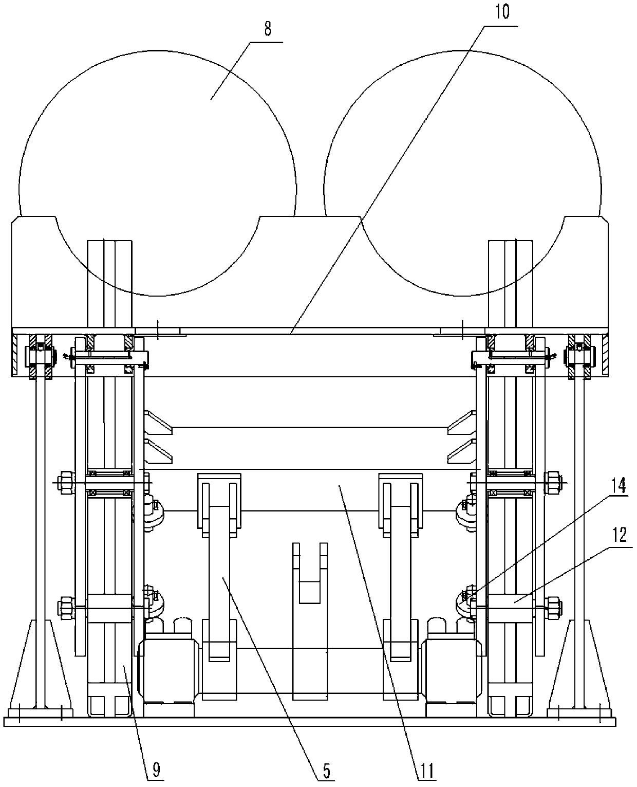
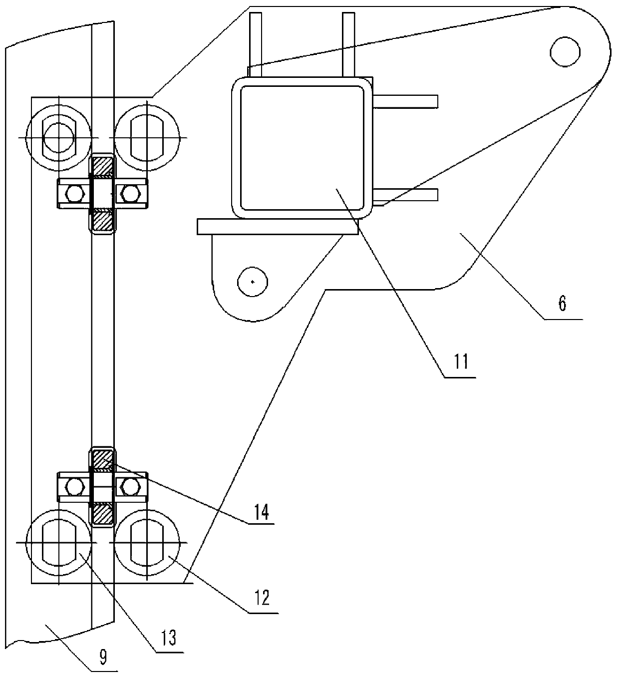
[0028] Such as figure 1 and figure 2 As shown, the wire reel frame 10 is arranged on the top of the main shaft 4, and the wire reel frame 10 in the horizontal state is positioned at the bottom on the inner side and is supported by the turning wheel 7 in a fixed position, and the turning wheel 7 is supported by the turning wheel frame on the machine. On the frame; the wire reel frame 10 is located at the bottom on the outside and is supported by the mobile plate 6, and the mobile plate 6 is hinged to the bottom of the wire reel frame 10 with its top;

[0029] A lifting mecha...


PUM


Abstract

The invention discloses a lateral-bottom-fed coil loading machine with a hydraulic rocker-slider mechanism. The lateral-bottom-fed coil feeding machine with the hydraulic rocker-slider mechanism is characterized in that a driving hydraulic cylinder is hinged to a transmission rocker though a piston rod end of the driving hydraulic cylinder, the transmission rocker is used for driving a spindle to rotate, a wire coil rack is disposed above the spindle, the horizontal wire coil rack located at the inner bottom is supported by a turning wheel at a fixed position, the turning wheel is supported on a frame through a turning wheel carrier, the wire coil rack located at outer bottom is supported by a moving plate, the moving plate is hinged to the bottom of the wire coil rack through the top end of the moving plate, a lifting mechanism is disposed between the wire coil rack and the spindle, guides are slanted, and the moving plate capable of moving up and down along the guides is limited on the guides through rollers. The hydraulic cylinder pushes the rocker-slider mechanism, the wire coil rack is used as a slider, and the lateral-bottom-fed coil loading machine is simple and reliable in structure and high in loading and unloading efficiency.

Description

technical field [0001] The invention relates to a reeling machine, more specifically, it is the equipment used in the cable production enterprises for carrying out the operation of reeling up and down the wire reel in the frame winch machine for producing stranded wires. Background technique [0002] The basic structure of the cable is composed of a conductive core and an insulating layer wrapped in the outer layer of the conductive core, a shielding layer, an armor layer, etc. As a power cable used to transmit electric energy to the grid, its conductive core is generally made of multiple copper or aluminum wires with circular cross-sections twisted, just like twisting a rope. Each single wire core is layered and twisted, and the conductive wire cores with a conventional circular cross section are layered and twisted according to 1, 6, 12, 18, 24, 30, and 36 wires. [0003] The frame stranding machine is one of the main equipments for making stranded conductive wire cores. ...

Claims


Application Information

Patent Timeline
Patent Type & Authority Applications(China)
IPC IPC(8): H01B13/02
Inventor 童兆耀岳光明周章银汪春春
Owner HEFEI SMARTER TECH GROUP CORP
Why Eureka
Try Eureka