Manufacturing method for manufacturing x-ray anode and x-ray anode thereof

An X-ray and anode technology, applied in the directions of X-ray tube electrodes, X-ray tube parts, X-ray tube targets and converters, etc., can solve the problems of high cost, uneven X-ray anode, high cost and so on, Achieve the effect of reducing stress distribution, shortening processing time, and minimizing crack structure

Active Publication Date: 2013-04-03
SIEMENS HEALTHCARE GMBH
View PDF5 Cites 0 Cited by
  • Summary
  • Abstract
  • Description
  • Claims
  • Application Information

AI Technical Summary

Problems solved by technology

[0009] A disadvantage of the known method is that x-ray anodes with inhomogeneous, in particular curved, surfaces can only be produced at great cost, since special molds are required for this
In addition, dimensional deviations can occur in particular in the edge region of curved surfaces, which leads to expensive and cost-intensive reworking

Method used


Image

  • Manufacturing method for manufacturing x-ray anode and x-ray anode thereof
  • Manufacturing method for manufacturing x-ray anode and x-ray anode thereof

Examples


Embodiment Construction

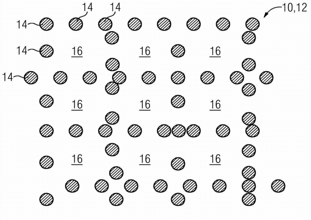
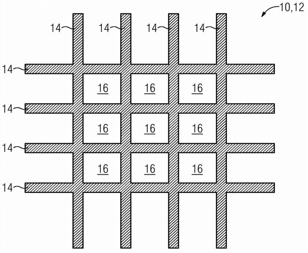
[0030] figure 1 A schematic top view of a focal region 10 of an x-ray anode 12 is shown, in which a microstructuring in the form of blind hole-like depressions 14 can be introduced by means of an ablation method. The depth of the depression 14 is between 50 μm and 100 μm, and it is arranged along a grid-like straight line, so that in principle, the figure 2 The checkerboard pattern shown in . Due to the aspect ratio achievable by means of the ablative method, it can thus be used as figure 2 Instead of the slit-shaped depressions 14 shown in , the "perforated" form of the edges of the island-like surface protrusions 16 produces a tessellated pattern. The distance between adjacent blind hole-shaped recesses 14 is approximately twice the bore diameter of the recesses 14 in the exemplary embodiment shown. As a result, the processing time of the x-ray system 10 can be significantly shortened, because during operation of the x-ray anode 12, in the focal area 10, the figure 2 ...


PUM

PropertyMeasurementUnit
depthaaaaaaaaaa
widthaaaaaaaaaa

Abstract

The present invention relates to a manufacturing method for manufacturing an X-ray anode and the X-ray anode therof. The X-ray anode (12) comprises a plurality of recess parts (14) which are introduced into the surface of an X-ray anode substrate in at least a focus area (10), wherein, each recess part (14) is introduced into the surface of the X-ray anode substrate through an ablation method. Hereon, blind-hole-shaped recess parts (14) are formed in the surface of the X-ray anode substrate through the ablation method, wherein, each recess part (14) is at least configured basically along grid-shaped lines. The invention further relates to an X-ray anode (12). The X-ray anode (12) comprises the recess parts (14) which are introduced into the surface of the X-ray anode substrate in the focus area (10). Furthermore the invention relates to application of the X-ray anode (12) in a set of X-ray equipment.

Description

technical field [0001] The invention relates to a method for producing an x-ray anode which has a structured surface at least in the region of its focal point, as well as an x-ray anode. Background technique [0002] When generating x-ray radiation, for example for medical applications, x-ray anodes, usually produced from metallic anode materials, are loaded with electrons. On reaching the x-ray anode, the electrons are strongly braked, whereby on the one hand x-ray radiation (so-called braking radiation) is formed and on the other hand heat is generated. But when a highly accelerated electron reaches the X-ray anode, only about one percent of the electron's kinetic energy is converted into X-ray radiation energy. The remaining energy is almost exclusively converted into heat and has to be conducted or radiated from the x-ray anode. The isostatic temperature profile within the x-ray anode is determined by the thermal power generated and the thermal conduction and radiation...

Claims


Application Information

Patent Timeline
Patent Type & Authority Applications(China)
IPC IPC(8): H01J9/02H01J35/10B23K26/36
CPCH01J9/02H01J2235/085H01J2235/086
Inventor J.弗罗伊登伯格S.兰彭舍夫S.沃尔特
Owner SIEMENS HEALTHCARE GMBH
Why Eureka
Try Eureka