Capacitive voltage division type self-triggering linear transformer driver

A capacitive voltage dividing and self-triggering technology, applied in the field of pulse power, to achieve the effect of reducing requirements, simple structure and reducing quantity

Inactive Publication Date: 2013-04-03
FUDAN UNIV
View PDF3 Cites 5 Cited by
  • Summary
  • Abstract
  • Description
  • Claims
  • Application Information

AI Technical Summary

Problems solved by technology

With the increase of the number of sub-blocks in the induction chamber and the number of series induction chambers, the number of switches tha

Method used


Image

  • Capacitive voltage division type self-triggering linear transformer driver
  • Capacitive voltage division type self-triggering linear transformer driver
  • Capacitive voltage division type self-triggering linear transformer driver

Examples


Embodiment Construction

[0024] The content of the present invention will be described in detail below in conjunction with the accompanying drawings and embodiments.

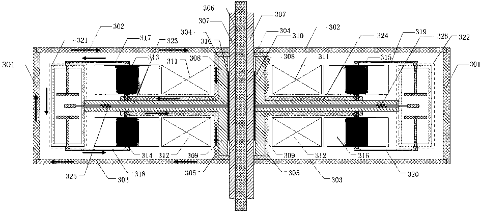
[0025] image 3 The working principle of the self-triggering LTD induction chamber shown is the same as that of the ordinary LTD induction chamber: first charge the capacitors 313, 314, 315, 316 positively and negatively, then the gas switches 321, 322 are turned on, and the current is in the direction indicated by the arrow in the figure flow. The capacitor and the magnetic cores 311 and 312 form a primary circuit for discharging, and couple the energy stored in the capacitor to the secondary metal bus bar 306 . The difference is that the common LTD sensing cavity conducts the gas switch through an external trigger, while the self-triggering LTD sensing cavity obtains a trigger signal from the trigger cylinder 310 through the principle of capacitive voltage division.

[0026]The central busbar 306, the metal trigger cylinder 301, the...


PUM


Abstract

The invention belongs to the technical field of pulse power, and particularly relates to a capacitive voltage division type self-triggering LTD (linear transformer driver). Common induction cavities and self-triggering induction cavities are serially connected by a secondary center bus bar to form the self-triggering LTD, the common induction cavities form a few front stages of the LTD, and the rest stages are the self-triggering induction cavities. The whole LTD can be triggered only by triggering the common induction cavities at the front stages when in operation. A metal triggering cylinder is added between inner metal and the secondary center bus bar in each common induction cavity, and insulating media are filled in two gaps, so that each self-triggering induction cavity is formed. The added metal triggering cylinders are used for realizing capacitive voltage division of the self-triggering induction cavities. The number of external triggering pulses can be effectively decreased, and the LTD is reliably triggered.

Description

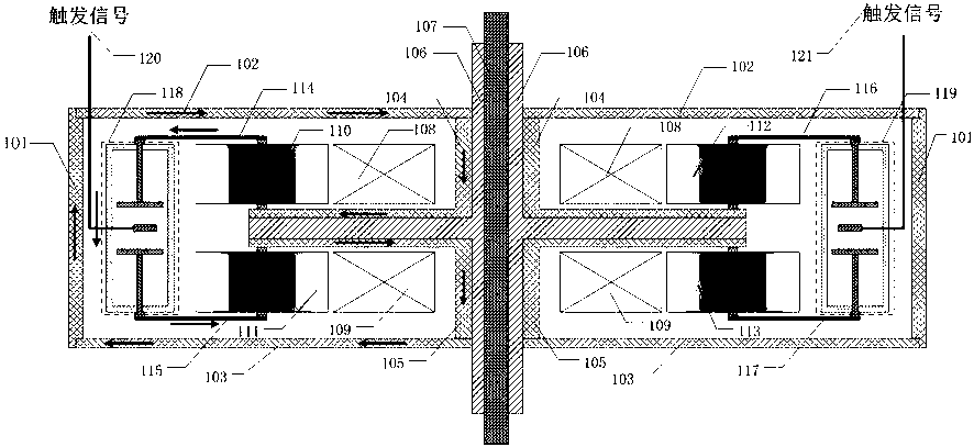
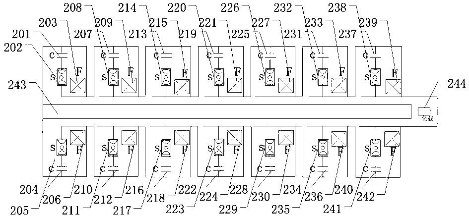
technical field [0001] The invention belongs to the technical field of pulse power, and in particular relates to a linear transformer driver (Linear Transformer Driver, LTD) which uses capacitive voltage division to realize switch self-triggering. Background technique [0002] LTD is a new pulse power technology capable of generating high power pulses with rise times around 100ns to drive loads directly without any pulse compression section. [0003] LTD consists of a switch and a capacitor (one-way charging) or two capacitors (positive and negative charging) in series to form a sub-block, several sub-blocks are connected in parallel to form an induction chamber, and several induction chambers are connected in series to form a module through induction superposition. figure 1 It is a sectional view of a single induction chamber. By increasing the number of parallel sub-blocks, a larger pulse current output can be generated, and a large pulse power device can be built. The p...

Claims


Application Information

Patent Timeline
IPC IPC(8): H02M9/00
Inventor 邱剑刘克富涂卓麟王永刚
Owner FUDAN UNIV
Why Eureka
Try Eureka