Combined type speaker system with front and back precise annular tube composite channels and multiple channels in back direction

A compound channel and annular tube technology, applied in the field of electroacoustics, to achieve the effects of improving fidelity and radiation efficiency, improving the environment in the channel, and reducing radiation distortion

Active Publication Date: 2013-04-03
石丰山
View PDF4 Cites 0 Cited by
  • Summary
  • Abstract
  • Description
  • Claims
  • Application Information

AI Technical Summary

Problems solved by technology

However, because there is a connection gap between the speaker frame, the upper magnetic guide plate and the magnet in the channel, and the upper end surface of the upper magnetic guide plate and the magnet has a reflective surface facing the vibrating body, this is formed by means of these exposed parts of the speaker. The channel is not smooth, and the sound waves are reflected here and cause distortion and sound energy loss. Due to the uncertainty of these distortions and sound energy loss, it affects the acoustic variable transducer implied by CA. The accuracy of the transformation effect
[0021]Third, the sound compliance component CA, the existing problems cause distortion and affect the radiation efficiency, which itself is also helpful for reducing the resonance frequency of the speaker Does not help and also complicates the equivalent circuit, which is not conducive to the simplification and intuitive analysis of the problem
The aforementioned distortion and loss of sound energy, affecting the quality and ability to reproduce sound

Method used


Image

  • Combined type speaker system with front and back precise annular tube composite channels and multiple channels in back direction
  • Combined type speaker system with front and back precise annular tube composite channels and multiple channels in back direction

Examples


Embodiment Construction

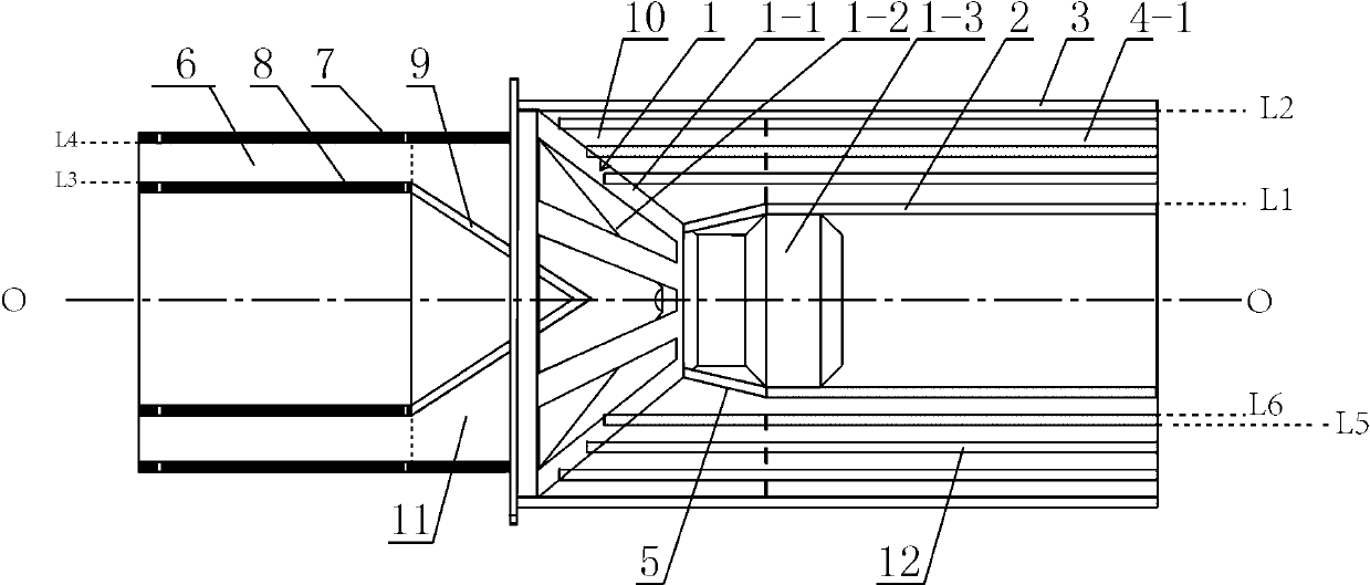
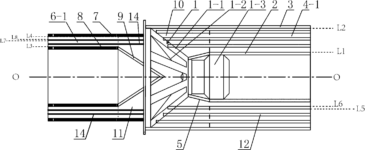
[0076] The intersection between the section of the axis O and the outer wall of the second inner tube 2 on one side is L1.The intersection lines on the inner wall of the middle sleeve 12 and the outer wall are L5, L6 on the same side of the L1; L1, L2, L5, and L6 can be parallel to each other.

[0077] It also includes the first inner tube 5 of the round platform with a stream of vibration paper basin 1-2 axis O as the center axis.Between the rear side of the radiation port, the first inner tube 5 back end is relatively aligned with the front end of the second inner tube 2.Round -shaped transition surface; the first inner tube 5 and the second inner tube 2 are smooth transitions.The first inner tube 5 can also be applied to the corresponding position with the paste, and it can be formed after solidification.

[0078] Install the direction of the direction of the direction and the rear-shaped tube channel in 4-1 in the rear tube channel unit 4-1.The passing channel between the bloc...


PUM


Abstract

The invention discloses a combined type speaker system with front and back precise annular tube composite channels and multiple channels in the back direction. By simultaneously mounting precise annular tube composite channels or channel group in the front and back of an alto cone loudspeaker and a bass cone loudspeaker, radiation environment of sound is limited, process of sound transmission radiation and output sound fields are affected, and fidelity and radiant efficiency of radiation sound saves in the front of and on the back of the loudspeakers are improved. When the loudspeaker works in low frequency, the precise annular tube composite channels in the front and back precise annular tube composite channels or channel group is formed by an annular tube sound transformer and an annular sound quality element, total equivalent vibrating quality of the loudspeakers is improved under the coactions of the sound transformer and the sound quality, low-frequency resonant frequency of the loudspeakers is reduced, and low-frequency radiation efficiency is further improved. Vibrators, surrounded by the precise annular tube composite channels and channel groups, of the loudspeakers are avoided from direct interference by external air, so that surface load equalization and front and back load equalization can be kept better, and dynamic reaction speed and the like can be increased.

Description

Technical field: [0001] After the invention, the composite speaker system of the precision ring tube composite channel is the front and rear of the multi -channel, which belongs to the field of electro -acoustic technology. Background technique: [0002] In daily life, people often use speakers to replace their sounds.Commonly used electric medium -sized medium -sized paper pot speakers (including bass, medium bass, medium sound speakers, and full -frequency belt speakers, also referred to as speakers below), the resonance frequency ω of the low -frequency resonance system of low -frequency force is completed. 0 It's OK, ω 0 Determine the lower limit of the sound frequency of this speaker, and usually uses a speaker that is installed on an unlimited barrier board as a reference, indicating that the speaker frequency ω ω ω 0 Wascable indicators.In this case, the speakers placed on the infinite barrier board can freely transmit sounds to the air in the two directions in the front ...

Claims


Application Information

Patent Timeline
IPC IPC(8): H04R9/06H04R9/02
Inventor 石丰山石杰
Owner 石丰山
Why Eureka
Try Eureka