Serpentine heat exchanger for an air conditioner

A technology for air conditioners and heat exchangers, which is applied in heat exchange equipment, heat sinks, heat transfer modification, etc., and can solve problems such as difficult air conditioners and heat exchangers

Active Publication Date: 2013-04-03
SUMITOMO LIGHT METAL INDS LTD
View PDF10 Cites 17 Cited by
  • Summary
  • Abstract
  • Description
  • Claims
  • Application Information

AI Technical Summary

Problems solved by technology

In view of such circumstances, it is difficult to directly apply heat exchangers for air conditioners...

Method used


Image

  • Serpentine heat exchanger for an air conditioner
  • Serpentine heat exchanger for an air conditioner
  • Serpentine heat exchanger for an air conditioner

Examples


Embodiment 1

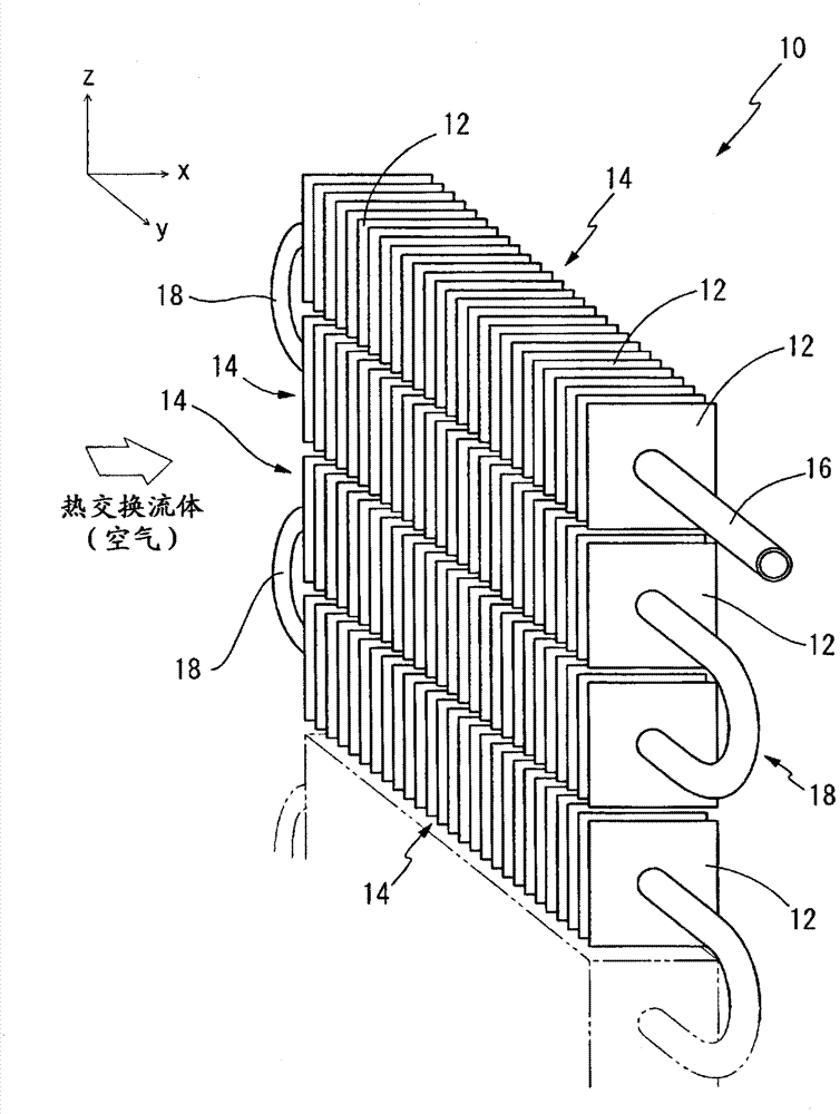
[0096] First, as the heat transfer tube for constituting the spiral heat exchanger for the air conditioner of the present invention, prepared is a material made of phosphorus-deoxidized copper, in which a plurality of inner surface grooves are formed as spiral grooves extending with a predetermined lead angle with respect to the tube axis. (JIS H3300 C1220) heat transfer pipe with grooves on the inner surface. The dimensions of the heat pipe with grooves on the inner surface are outer diameter: 6.35 mm, bottom wall thickness: 0.23 mm, groove depth: 0.15 mm, number of grooves: 58, and lead angle: 30°.

[0097] On the other hand, as a fin material, a plate material of pure aluminum (JIS A1050) with a plate thickness of 0.13 mm was prepared, and the surface of the fin material was subjected to the following steps: Figure 4 The surface treatment shown consists of 3 layers. That is, first, the chemical conversion coating 32 made of phosphochromate is formed on the surface of the ...

experiment example 2

[0109] Various spiral heat exchangers are produced as follows, that is, as the fin material, a plate of pure aluminum (JIS A1050) with a plate thickness of 0.12 mm is used, and a film thickness of 0.1 μm formed on the surface of the plate is made of phosphorus On the chemical conversion film (substrate treatment layer) made of chromate, a hydrophobic coating layer made of fluororesin, a hydrophilic coating layer made of polyurethane resin or The hydrophobic coating layer made of silicone resin, on the other hand, as the heat transfer tube, except that the inner surface grooved heat transfer tube made of phosphorus deoxidized copper (JIS H3300 C1220) with an outer diameter of 7.00 mm is used, which is different from the previous one. In the same manner as in Experimental Example 1, 16 fin groups with a fin pitch of 3.0 mm were arranged (the number of fins per one fin group was 100 sheets).

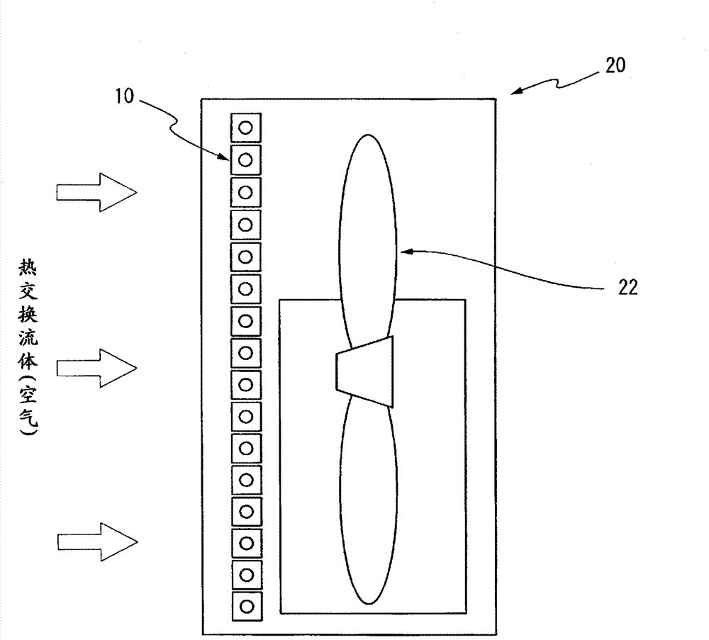
[0110] Next, the obtained various heat exchangers such as figure 2 It was fixed to a ...

experiment example 3

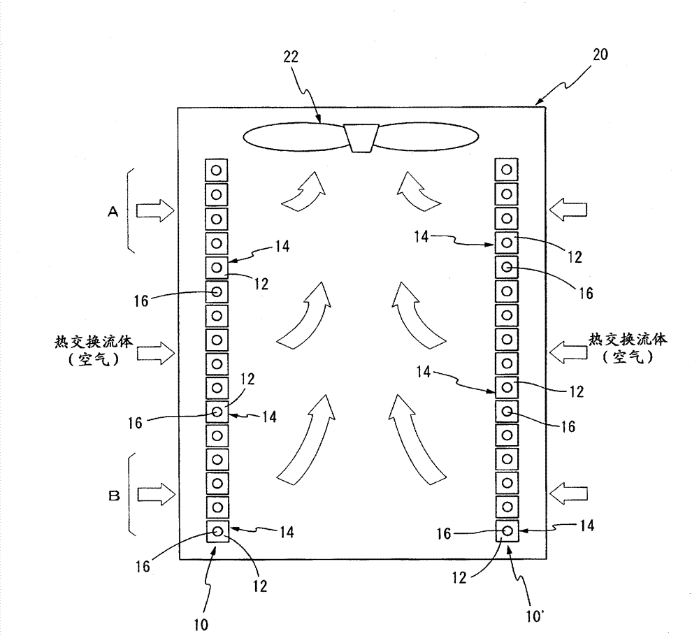
[0112] Made it as follows Figure 5 For the spiral heat exchanger of the shape shown, the fin material with the hydrophilic resin coating film formed on the surface and the heat transfer tube with grooves on the inner surface are prepared as in the above-mentioned Example 2, and the fin size is 12 mm. ×50mm (fin projection area is 600mm 2 ), with respect to one sheet of the fins running through two heat pipes. In addition, the pitch of fins, the number of fins, the number of layers of fin groups, and the like are the same as those of the heat exchanger of Example 2. Such a heat exchanger was fixed to a predetermined outdoor unit in the same manner as the heat exchanger of Example 2, and the presence or absence of splashing water and the heat exchange performance were checked. As a result, it was confirmed that good results were obtained in all of them.


PUM

PropertyMeasurementUnit
Shadow areaaaaaaaaaaa
Outer diameteraaaaaaaaaa
Diameteraaaaaaaaaa

Abstract

The disclosed serpentine heat exchanger for an air conditioner effectively minimizes losses in heat-exchange performance due to condensation and is capable of adequately accommodating efforts to reduce the size of air conditioners. Said serpentine heat exchanger (10) comprises a plurality of fin groups (14) and a heat-exchanger pipe (16). Each fin group (14) is formed by arranging a large number of fins (12), each comprising a metal plate with a prescribed coating layer formed on at least one surface, parallel to each other at intervals of 0.6-5.0 mm in a direction (y direction) perpendicular to the direction (x direction) in which a heat-exchange fluid, namely air, flows. The plurality of fin groups (14) are arranged in a row at a constant distance from each other in a direction (z direction) perpendicular to the x direction and the y direction. The heat-exchanger pipe (16) is laid out in a serpentine configuration so as to penetrate each fin group (14) in turn.

Description

technical field [0001] The present invention relates to a spiral heat exchanger for exchanging heat between a heat exchange fluid such as air and a refrigerant, and particularly relates to a spiral heat exchanger suitable for use as a heat exchanger for an air conditioner. Background technique [0002] Conventionally, cross-fin-tube heat exchangers have been mainly used as heat exchangers for air conditioners. The cross-fin-tube heat exchanger is constructed by inserting a plurality of heat transfer tubes bent in a hairpin shape into the plurality of fins in a direction perpendicular to the plurality of fins, and expanding the heat transfer tubes so that The fins and heat pipes are joined. In such a heat exchanger, a predetermined refrigerant flows through the heat transfer tubes, while air flows along the fins in a direction perpendicular to the heat transfer tubes, thereby exchanging heat between the refrigerant and the air. [0003] In addition, such a cross-fin-tube he...

Claims


Application Information

Patent Timeline
IPC IPC(8): F28F1/32F28F1/40F28F13/02F28F21/08
CPCF28D2021/0071F28F2215/10F28F1/32F28F2245/04F28F21/084F28F1/24F28D1/0477F28F21/085F28F19/04F28F19/06F28F1/40F28F2245/02
Inventor 佐佐木直荣矶村纪寿片平史郎
Owner SUMITOMO LIGHT METAL INDS LTD
Why Eureka
Try Eureka