Rotary electrical device, bearing attachment and detachment tool, and bearing replacement method

A technology of rotating motors and fixtures, which is applied in the direction of rotating bearings, bearings, motors, etc., can solve the problems of unstable rotors, difficult to fix rotors, defects, etc., and achieve the effect of easy loading and unloading operations

Active Publication Date: 2015-06-17
MITSUBISHI ELECTRIC CORP
View PDF9 Cites 0 Cited by
  • Summary
  • Abstract
  • Description
  • Claims
  • Application Information

AI Technical Summary

Problems solved by technology

[0006] However, according to the above-mentioned prior art, since the rotor is supported by the frictional force of the front end of the bolt inserted from the bearing bracket, there is a problem that it is difficult to fix the rotor stably only by the frictional force.
Furthermore, according to the above-mentioned prior art, since the bolts are relatively long, the rotor fixed by the bolts may become unstable due to the deflection of the bolts.
In this case, since the axial center position of the rotor is displaced from the axial center position of the frame, not only the inner peripheral surface of the stator core may be damaged due to contact with the outer peripheral surface of the rotor, but also the attachment and detachment of the bearing may be difficult. The problem

Method used


Image

  • Rotary electrical device, bearing attachment and detachment tool, and bearing replacement method
  • Rotary electrical device, bearing attachment and detachment tool, and bearing replacement method
  • Rotary electrical device, bearing attachment and detachment tool, and bearing replacement method

Examples


Embodiment approach

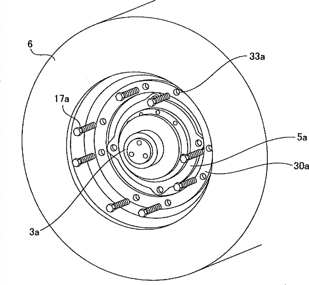
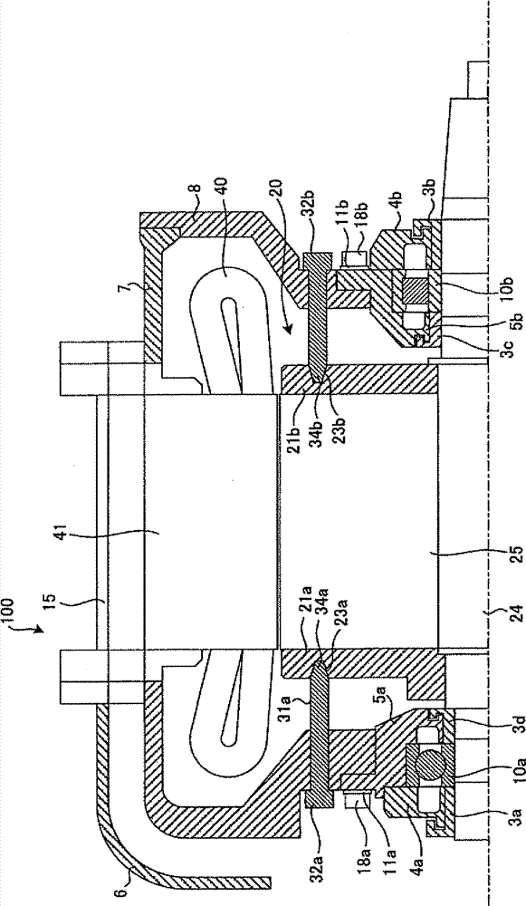
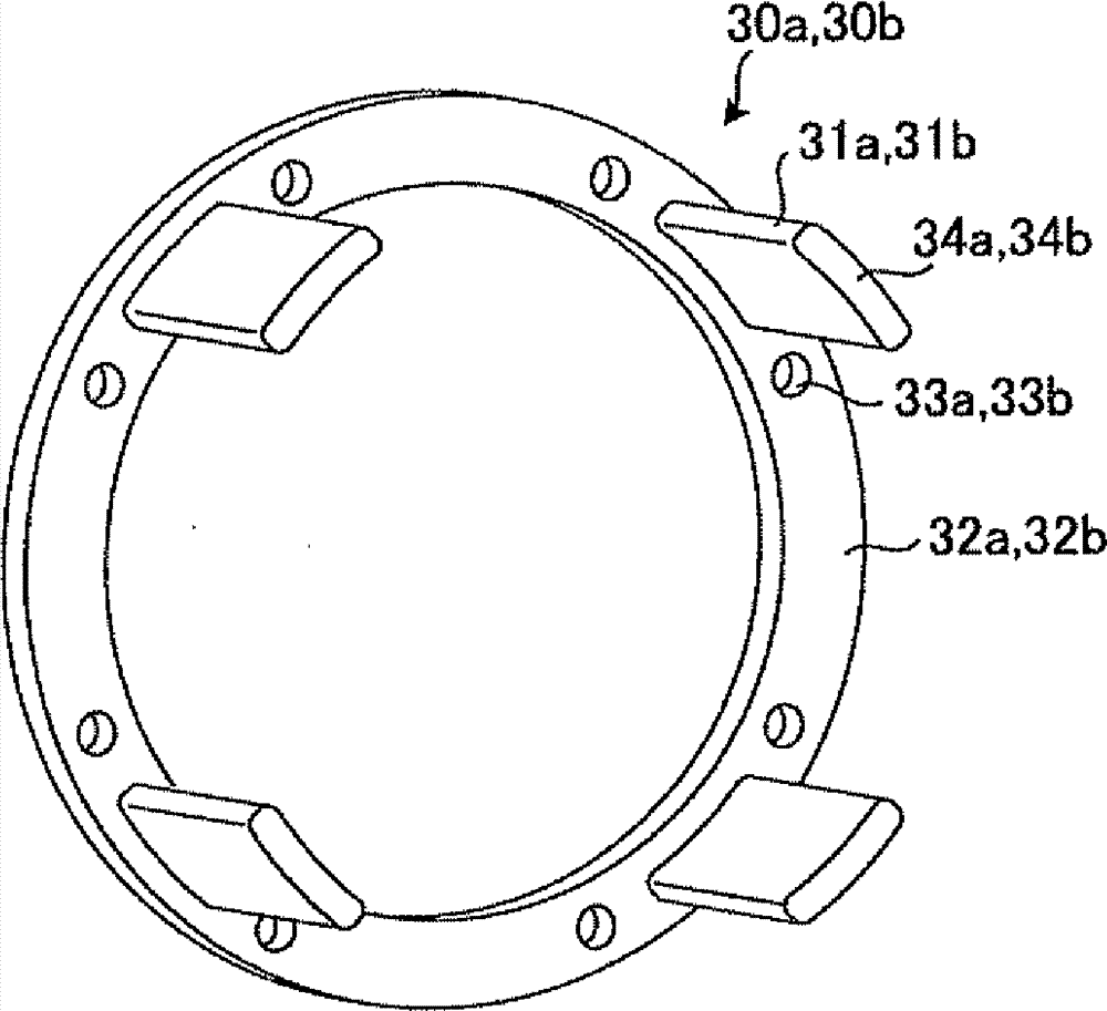
[0029] figure 1 is a longitudinal sectional view of the rotating electric machine 100 according to the embodiment of the present invention, figure 2 It is a figure which shows the structure of the ring-shaped jig 30. image 3 It is a perspective view of the rotor 20 shown centering on the iron core holding plate 21a on the opposite driving side, Figure 4 It is a drawing for explaining the shape of the recesses 23a, 23b formed in the core holder 21a on the opposite driving side or the core holder 21b on the driving side, and the shape of the ends of the rotor supporting parts (supporting parts) 31a, 31b.

[0030] In the following description, the figure 1 The structure of the rotating electrical machine 100 shown is described, after which, using figure 2 Carry out the description related to the ring-shaped clamps 30a, 30b, while using image 3 The structure of the rotor 20 will be described. In addition, in order to explain the structure of the rotating electric machi...


PUM


Abstract

To provide a rotary electric machine 100 including a stator iron core 41, a rotor 20 including a lamination core 25 that is arranged within the stator iron core 41 and is constituted by laminating electromagnetic steel plates and an iron core holder 21a and an iron core holder 21b that cover both ends of the lamination core 25, a frame 15 including a cylindrical portion that encloses the stator iron core 41 and the rotor 20 and a rotor-shaft supporting unit that extend portions in a direction of a rotor shaft 24 and supports the rotor shaft 24, and cartridges 5a and 5b that are detachably attached to the rotor-shaft supporting unit and rotatably support the rotor shaft 24, in which on the iron core holder 21a and the iron core holder 21b, recessed portions (23a and 23b) are circumferentially provided, into which end portions (34a, 34b, and 53) of jigs (30a, 30b, and 50) that are inserted through the rotor-shaft supporting unit to enable the cartridges 5a and 5b to be detached and attached are fitted.

Description

technical field [0001] The present invention relates to a rotating electric machine for driving a railway vehicle, a jig for mounting and dismounting a bearing, and a method for replacing a bearing. Background technique [0002] Among rotating electric machines for railway vehicles, a fully enclosed rotating electric machine is generally used from the viewpoint of saving maintenance. This fully-sealed rotating electric machine mainly includes a cylindrical frame with a rotor arranged on the inner peripheral side, and a casing that is mounted opposite to both ends of the frame and supports the rotor shaft in a rotatable manner. A bearing is provided in the center of the housing, and a cylindrical stator core for accommodating the stator coil is installed on the inner periphery of the frame, and a uniform gap is formed between the inner peripheral surface of the stator core and the outer peripheral surface of the rotor. void. [0003] The hermetically sealed rotating electri...

Claims


Application Information

Patent Timeline
Patent Type & Authority Patents(China)
IPC IPC(8): H02K5/04H02K5/173
CPCH02K5/1732H02K15/0006H02K15/14H02K15/16F16C35/045F16C35/062F16C35/077F16C19/54F16C2380/26B60L2220/50Y10T29/53143Y02T10/64H02K5/207H02K5/173H02K5/04H02K9/06B60K6/00H02K5/16
Inventor 金子健太
Owner MITSUBISHI ELECTRIC CORP
Why Eureka
Try Eureka