Flanging die

A flanging mold and template technology, applied in the field of flanging molds, can solve the problems of poor flanging effect and high manufacturing cost, and achieve the effects of high processing efficiency, reasonable structural design, and wide adaptability

Inactive Publication Date: 2013-04-10
芜湖中山科技有限公司
View PDF11 Cites 4 Cited by
  • Summary
  • Abstract
  • Description
  • Claims
  • Application Information

AI Technical Summary

Problems solved by technology

However, there are many defects such as high manufacturing cost and poor flanging effect.

Method used


Image

  • Flanging die

Examples


Embodiment Construction

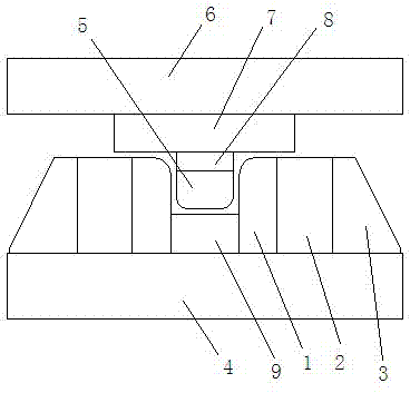
[0013] see figure 1 , flanging mold, has upper mold 6 and lower mold 4 that are arranged up and down, upper mold 6 bottom is provided with upper formwork 7, the bottom of upper formwork 7 is provided with backing plate 8, and the bottom of backing plate 8 is provided with embossing mod 5.

[0014] The upper part of the lower mold 4 is provided with a ring-shaped first lower template 3, the inner side of the first lower template 3 is provided with a ring-shaped second lower template 2, and the inner side of the second lower template 2 is provided with a ring-shaped third lower template 1 , The inner side of the third lower template 1 is provided with a die 9 .

[0015] When the upper mold 6 and the lower mold 4 are close, the male mold 5 is inserted into the female mold 9 , and the two sides of the male mold 5 are against the inner side of the third lower template 1 .

[0016] The material of upper die 6 and lower die 4 is A3 steel, and the materials of upper die 7, backing p...


PUM


Abstract

The invention relates to an automobile part machining die, in particular to a flanging die, which is provided with an upper die and a lower die which are respectively arranged from the upper part to the lower part. An upper die plate is arranged at the bottom of the upper die. A cushion plate is arranged at the bottom of the upper die plate. A male die is arranged at the bottom of the cushion plate. A first annular lower die plate is arranged at the upper part of the lower die. A second annular lower die plate is arranged on the internal side of the first lower die plate. A third annular lower die plate is arranged on the internal side of the second lower die plate. A female die is arranged on the internal side of the third lower die plate. When the upper die and the lower die get close to each other, the male die is inserted into the female die and the two sides of the male die press against the internal side of the third lower die plate. The upper die and the lower die are made of A3 steel. The upper die plate, the cushion plate, the first lower die plate, the second lower die plate and the third lower die plate are made of No.45 steel. The flanging die provided by the invention has the advantages that the structural design is reasonable, the machining efficiency is high, the flanging effect is good and the application scope is wider.

Description

technical field [0001] The invention relates to a mold for processing automobile parts, in particular to a flanging mold. Background technique [0002] In the field of auto parts processing, there are various structures of the flanging dies used for forming the fixing bracket of the auto fuel tank bracket. However, there are many defects such as high manufacturing cost and poor flanging effect. In order to improve the performance of the mold, the present invention aims to provide a flanging mold with excellent structural performance and low manufacturing cost. Contents of the invention [0003] Aiming at the technical problems in the prior art, the invention provides a flanging die with simple and reasonable structural design. [0004] In order to achieve the above purpose, the technical scheme adopted is as follows: [0005] The flanging die is characterized in that it has an upper die and a lower die arranged upper and lower, [0006] The bottom of the upper mold is ...

Claims


Application Information

Patent Timeline
Patent Type & Authority Applications(China)
IPC IPC(8): B21D37/10
Inventor 钱炳南昂彬褚培
Owner 芜湖中山科技有限公司
Why Eureka
Try Eureka