
Laser output adjustment device and method

A technology of output adjustment and laser, which is applied in the direction of lasers, laser welding equipment, laser parts, etc., can solve problems such as difficult judgment and laser beam adjustment, and achieve the effect of enhancing reliability and stability

Active Publication Date: 2015-11-04
CHARM ENG CO LTD
View PDF6 Cites 0 Cited by
  • Summary
  • Abstract
  • Description
  • Claims
  • Application Information

AI Technical Summary

Problems solved by technology

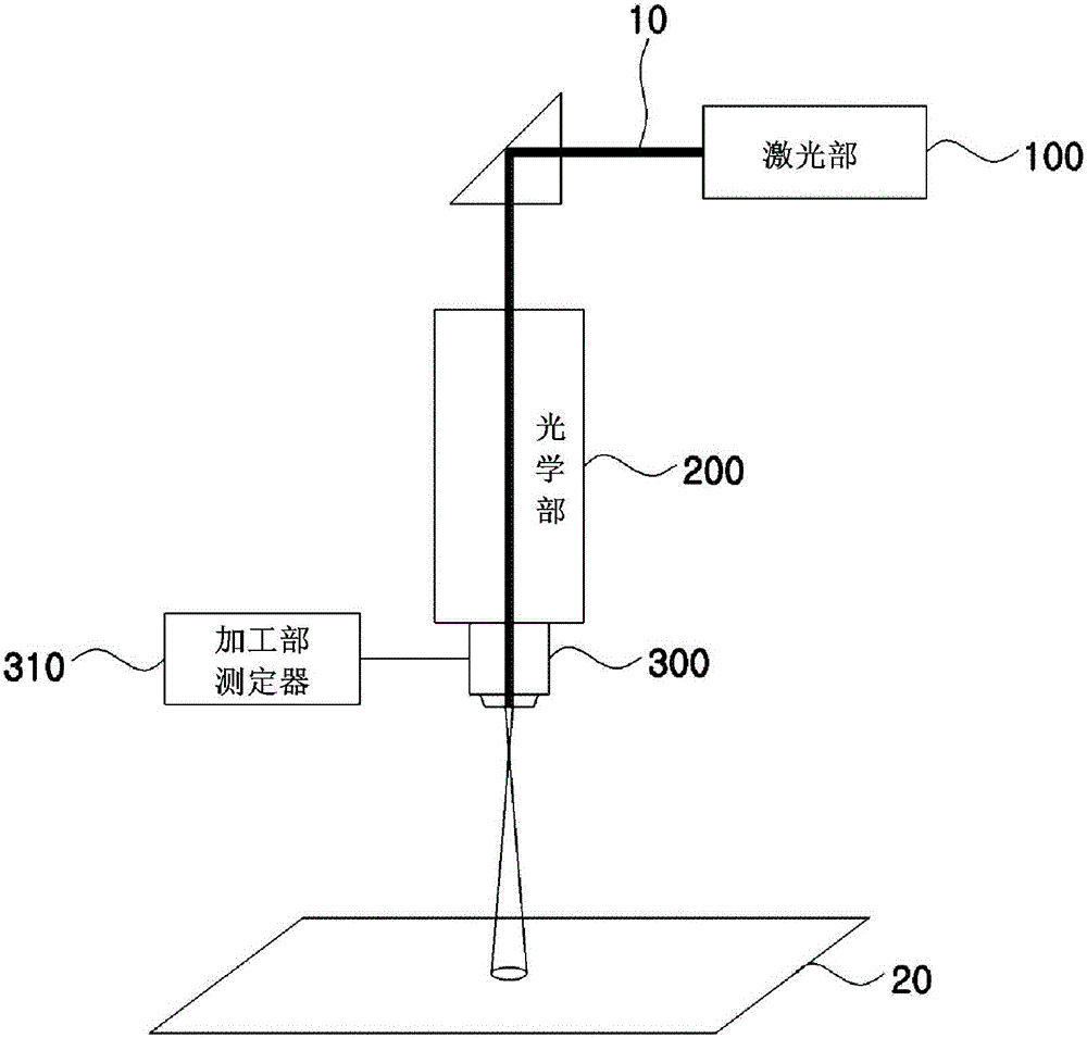
But when the phenomenon that the output energy of the laser beam 10 decreases occurs, it is difficult to judge the position that causes the output energy of the laser beam 10 to decrease.
In addition, there is also the difficulty of readjusting the reduced output energy of the laser beam to the desired intensity

Method used


Image

  • Laser output adjustment device and method
  • Laser output adjustment device and method
  • Laser output adjustment device and method

Examples


Embodiment Construction

[0037] Hereinafter, specific embodiments in which the present invention can be implemented will be illustrated and described in detail with reference to the accompanying drawings. These examples are described in detail in order to enable those skilled in the art to fully practice the invention. The various embodiments of the invention, although different, are not mutually exclusive. For example, specific shapes, specific structures and characteristics described here are related to one embodiment, and can also be embodied by other embodiments without departing from the spirit and scope of the present invention. In addition, the positions or arrangements of individual structural components in the respective disclosed embodiments may be changed without departing from the spirit and scope of the present invention. Therefore, the following detailed description is not intended to be limiting. As long as it is reasonably stated, the scope of the present invention is only limited to ...


PUM


Abstract

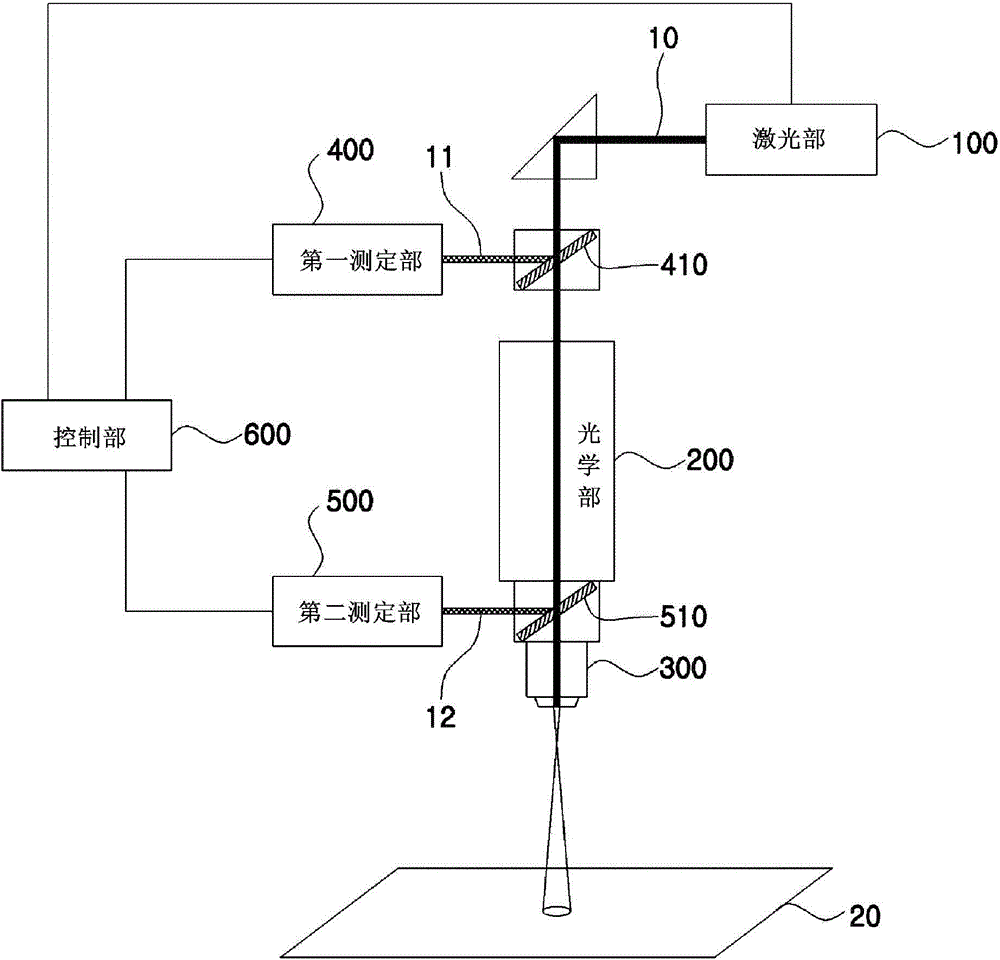
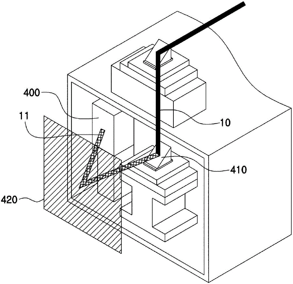
PURPOSE: A laser output adjustment apparatus and a method thereof are provided to easily adjust an output of a laser beam irradiated in a substrate. CONSTITUTION: A laser unit(100) generates a laser beam(10). An optical unit(200) provides a path of the laser beam. A processing unit(300) irradiates the laser beam passing the optical unit in a substrate(20). A first measurement unit(400) is arranged between the laser unit and the optical unit and measures an output of the laser beam generated from the laser unit. A second measurement unit(500) is arranged within the optical unit and measures the output of the laser beam passing the optical unit. A controlling unit(600) receives an output signal of the laser beam measured in the first measurement unit and the second measurement unit, transmits the signal to the laser unit, and adjusts the output of the laser beam generated from the laser unit. [Reference numerals] (100) Laser unit; (200) Optical unit; (400) First measurement unit; (500) Second measurement unit; (600) Controlling unit;

Description

technical field [0001] The invention relates to a laser output adjustment device and method. More specifically, it is a laser output adjustment device and method capable of easily adjusting the output energy of the laser beam irradiated on a substrate by measuring the laser beam generated in the laser unit by the first measurement unit and the second measurement unit. Background technique [0002] In recent years, with the increase in demand and the trend of large-scale flat panel display devices, especially in liquid crystal displays (LCD), the application degree, size increase and resolution increase speed are also accelerating, and in order to improve production efficiency and Achieving low prices has put a lot of effort into simplifying the manufacturing process and increasing yield. The basic structure of a liquid crystal display consists of an upper substrate formed with a black matrix, a color filter film, and a common electrode, and a lower substrate formed with pix...

Claims


Application Information

Patent Timeline
Patent Type & Authority Patents(China)
IPC IPC(8): B23K26/062B23K26/03
CPCB23K26/03B23K26/067H01S3/10H01S3/13
Inventor 郑薰尹星进金俊来李伦在金铉洙池泳洙
Owner CHARM ENG CO LTD
Learn More