Auxiliary support device for milling machine

An auxiliary support and milling machine technology, applied in milling machine equipment, milling machine equipment details, large fixed members, etc., can solve problems such as time-consuming and laborious, limited milling machine feed, affecting normal production, etc., to improve work efficiency, realize automatic milling, The effect of increasing the width

Active Publication Date: 2015-09-02
LAIWU IRON & STEEL GRP
View PDF8 Cites 0 Cited by
  • Summary
  • Abstract
  • Description
  • Claims
  • Application Information

AI Technical Summary

Problems solved by technology

In the process of using a milling machine to process super-long parts, such as the F-shaped steel used for the rail row of a maglev train of 10m, due to the limited feed of the milling machine on the Y-axis, relying solely on the worktable of the milling machine itself will not be able to realize the long parts. processing
[0003] For the rail row of the maglev train, the F-shaped steel on the two parallel rail rows has a symmetrical structure. In the process of processing, in order to adapt to the fixed structure of the fixture on the milling machine, it is often necessary to replace the head and tail of the F-shaped steel, which is not only time-consuming and laborious. , but also makes the processing efficiency of F-shaped steel lower, affecting normal production

Method used


Image

  • Auxiliary support device for milling machine
  • Auxiliary support device for milling machine
  • Auxiliary support device for milling machine

Examples


Embodiment Construction

[0025] The present invention will be further described below in conjunction with the accompanying drawings and embodiments.

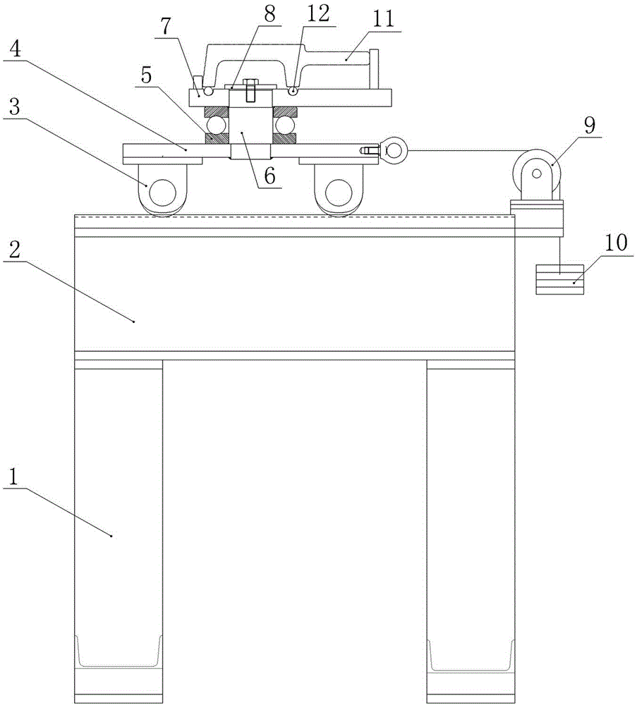
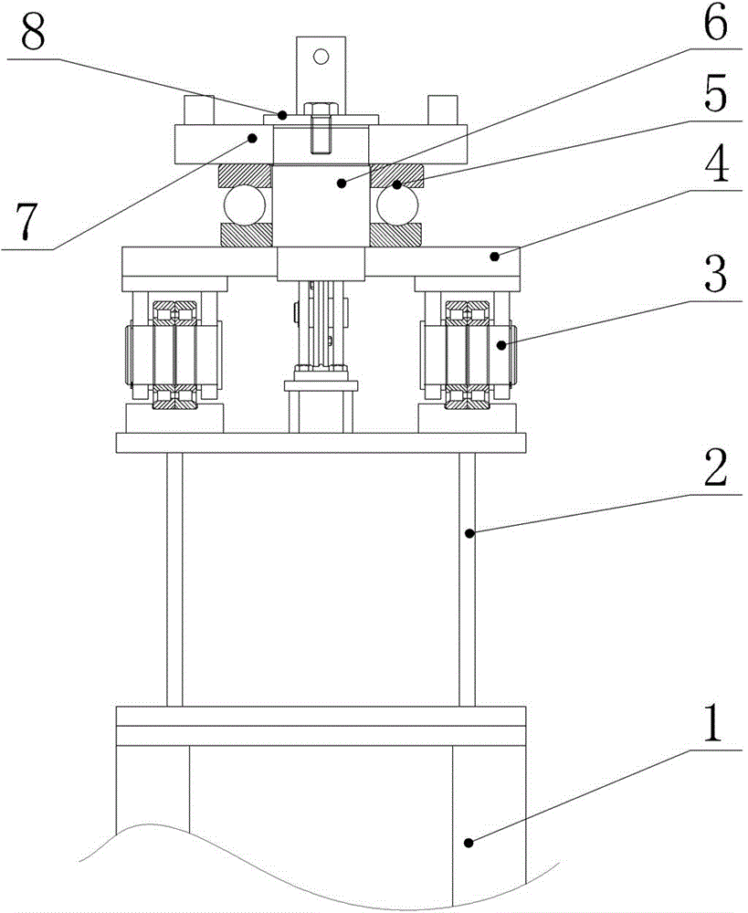
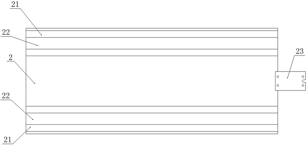
[0026] like figure 1 and figure 2 As shown, the front view and the left side view of the milling machine auxiliary support device of the present invention are provided respectively, which include a support 1, a base 2, a support wheel 3, a lower support plate 4, a bearing 5, a support shaft 6, and an upper support plate 7 , pressing plate 8, fixed pulley 9, counterweight 10. The shown base 2 is fixed above the support 1, and the support 1 is fixed on the foundation; image 3 and Figure 4 A top view and a left side view of the base 2 are given. Guide rails 21 parallel to each other are arranged along the length direction of the base 2 , and guide rail grooves 22 are opened on the guide rails 21 . Four support wheels 3 are fixed on the four corners of the lower surface of the lower support plate 4, and the bottom of the support wheels 3 is placed in...


PUM


Abstract

The invention discloses an auxiliary support device for a milling machine. The auxiliary support device comprises a base, support wheels, a lower support plate, and an upper support plate for fixing a part to be processed, and is characterized in that the base is provided with guide rails; the four support wheels are fixed on the lower support plate; the lower support plate is provided with a lower axle hole which is fixed together with the lower end of a support shaft; the upper support plate is provided with an upper axle hole which is in clearance fit with the upper end of the support shaft; the top end of the support shaft is provided with a pressure plate for limiting the upper support plate; and the upper support plate is provided with a clamp structure. Due to the adoption of the auxiliary support device for the milling machine disclosed by the invention, supporting of to-be-processed workpieces is realized, and automatic milling processing of the workpieces is realized; and the width of a workpiece processed by using the milling machine is increased. The upper support plate rotates relative to the lower support plate, so that clamping of long workpieces with symmetrical structures such as F-shaped steel for magnetically levitated train track sections can be realized effectively, the head and tail of F-shaped steel are not required to be reversed, time and labor are saved, and the working efficiency is increased.

Description

technical field [0001] The invention relates to an auxiliary supporting device for a milling machine, and more specifically relates to an auxiliary supporting device for a milling machine suitable for processing long workpieces. Background technique [0002] Milling machines are mainly machine tools that use milling cutters to process various surfaces on workpieces. The main movement of the milling cutter is rotary motion. It can process planes, grooves, various curved surfaces, gears, etc. In the process of using a milling machine to process super-long parts, such as the F-shaped steel used for the rail row of a maglev train of 10m, due to the limited feed of the milling machine on the Y-axis, relying solely on the worktable of the milling machine itself will not be able to realize the long parts. processing. [0003] For the maglev train rail row, the F-shaped steel on the two parallel rail rows has a symmetrical structure. In the process of processing, in order to ...

Claims


Application Information

Patent Timeline
Patent Type & Authority Patents(China)
IPC IPC(8): B23Q1/72B23C9/00
Inventor 姬生永江代更李元才
Owner LAIWU IRON & STEEL GRP
Why Eureka
Try Eureka