
Special milling machine for square riser

A square and riser technology, applied in the field of square riser milling machines, can solve the problems of poor operating environment, low grinding efficiency, and major safety hazards for operators, so as to eliminate safety hazards, improve machining accuracy and quality, and reduce labor. the effect of strength

Inactive Publication Date: 2018-01-30
JINAN MEIDE CASTING CO LTD
View PDF0 Cites 0 Cited by
  • Summary
  • Abstract
  • Description
  • Claims
  • Application Information

AI Technical Summary

Problems solved by technology

[0002] At present, manual grinders are commonly used for square riser milling. The grinding wheel is driven by the motor, and the operator holds the square riser for grinding. There are great safety hazards. The operating environment of the operator is poor, the grinding efficiency is low, and the labor intensity is high.

Method used


Image

  • Special milling machine for square riser
  • Special milling machine for square riser
  • Special milling machine for square riser

Examples


Embodiment 1

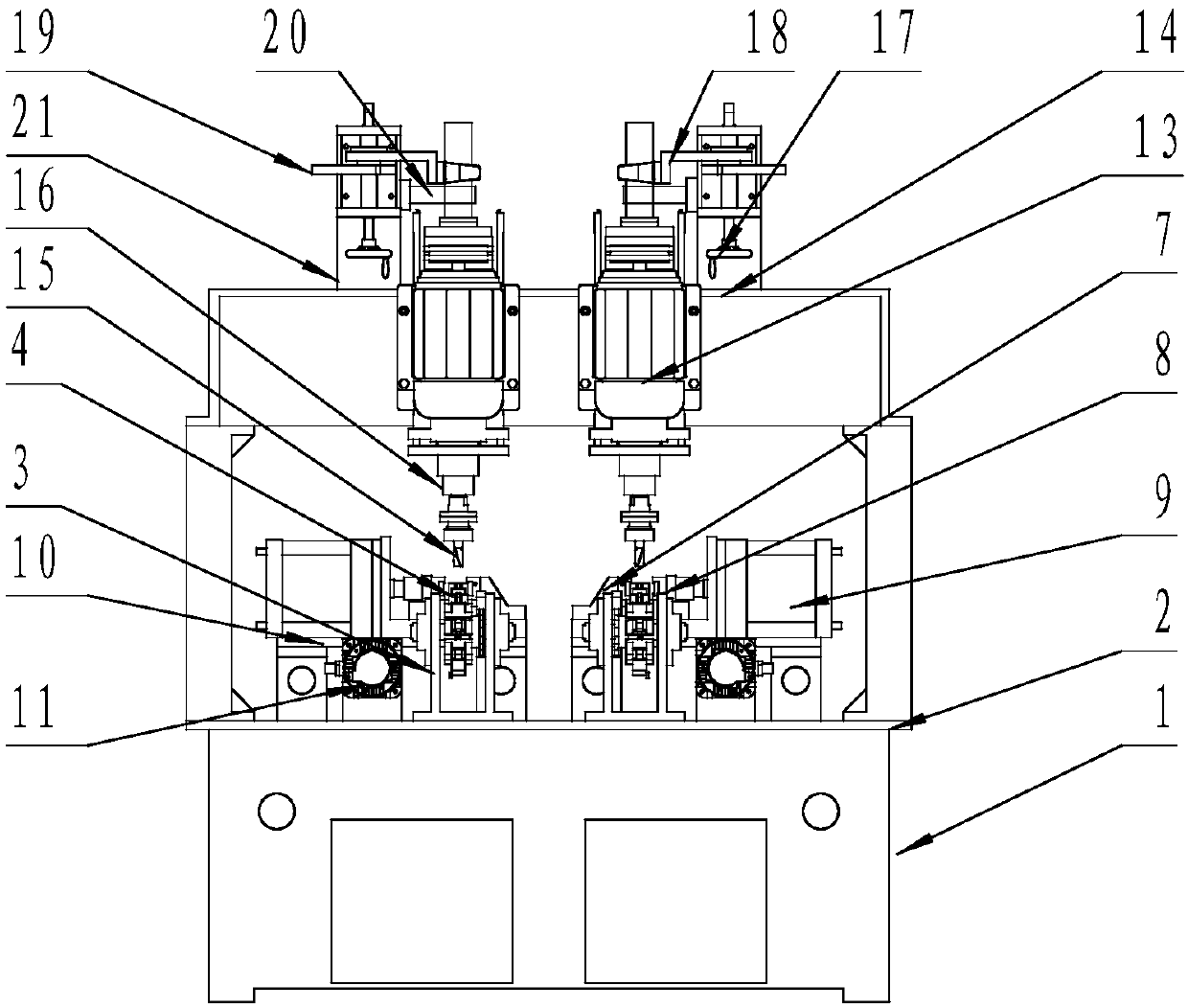
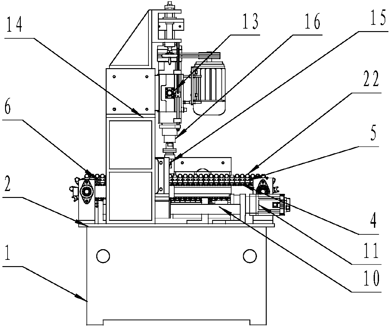
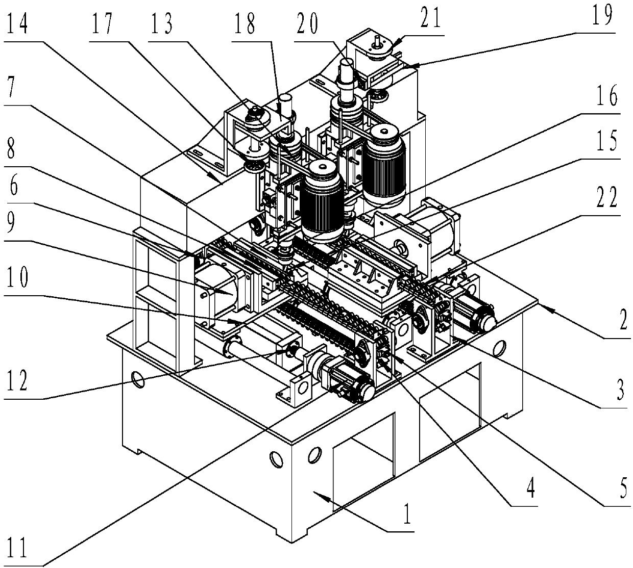
[0020] Such as figure 1 , figure 2 , image 3 As shown, a special square riser milling machine includes a frame 1 and a workbench 2 installed on the frame 1. It is characterized in that it includes two square risers symmetrically and longitudinally installed on both sides of the center line of the top surface of the workbench. Milling device; the square riser milling device includes a square riser conveying device, a square riser clamping device and a pushing operation device of the square riser clamping device, a square riser milling power unit and a stroke of the square riser milling power unit Control devices; also include air pressure and electrical devices;

[0021] The square riser conveying device comprises a strip frame 3, double ear chain 4, square riser seat 5, and the top surface of the square riser seat 5 is provided with a U-shaped groove for accommodating the square riser. The bar frame 3 is vertically installed on the top surface of one side of the workbench...

Embodiment 2

[0025] Such as figure 1 , figure 2 , image 3 As shown, a special square riser milling machine includes a frame 1 and a workbench 2 installed on the frame 1. It is characterized in that it includes two square risers symmetrically and longitudinally installed on both sides of the center line of the top surface of the workbench. Milling device; the square riser milling device includes a square riser conveying device, a square riser clamping device and a pushing operation device of the square riser clamping device, a square riser milling power unit and a stroke of the square riser milling power unit Control devices; also include air pressure and electrical devices;

[0026] The square riser conveying device comprises a strip frame 3, double ear chain 4, square riser seat 5, and the top surface of the square riser seat 5 is provided with a U-shaped groove for accommodating the square riser. The bar frame 3 is vertically installed on the top surface of one side of the workbench...


PUM


Abstract

The invention discloses a special milling machine for a square riser. The special milling machine for the square riser comprises a rack and a working platform installed on the rack, and comprises twosquare riser milling devices symmetrically and longitudinally installed on the two sides of the central line of the top surface of the working platform, and the square riser milling device comprises asquare riser conveying device, a square riser clamping device, a pushing running device of the square riser clamping device, a square riser milling power device, and a stroke control device of the square riser milling power device. The square riser is automatically milled, the milling working efficiency of the square riser is improved, the potential safety hazard in the milling of the square riser is further eliminated, the operation environment of an operating worker is improved, the labor intensity of the operating worker is reduced, the machining precision and quality of automatic millingof the square riser is also improved, and a square riser placing base with a U-shaped groove for accommodating the square riser can also be conveniently changed to adapt to the square risers with different specifications to mill.

Description

technical field [0001] The invention belongs to a special machine for milling a riser, in particular to a special machine for milling a square riser. Background technique [0002] At present, manual grinders are generally used for square riser milling. The grinding wheel is driven by a motor, and the operator holds the square riser for grinding. There are great safety hazards. The operating environment of the operator is poor, the grinding efficiency is low, and the labor intensity is high. How to realize the automatic milling of square risers, improve the efficiency of square riser milling, eliminate the safety hazards of square riser milling, improve the working environment of operators, and reduce the labor intensity of operators are problems that need to be solved. Contents of the invention [0003] The technical problem to be solved by the present invention is to provide a special machine for milling square risers. The square riser milling special machine can realize...

Claims


Application Information

Patent Timeline
Patent Type & Authority Applications(China)
IPC IPC(8): B23C1/08B23C3/00B23Q3/08
Inventor 周生连韩海卫刘玉光
Owner JINAN MEIDE CASTING CO LTD
Learn More