

Bidirectional clamping device
A two-way clamping and clamping technology, applied in positioning devices, clamping, supporting and other directions, can solve the problems of unstable positioning, the workpiece cannot meet the processing requirements, and the position of the workpiece is offset, and achieves convenient operation and simple structure. , more accurate positioning effect
- Summary
- Abstract
- Description
- Claims
- Application Information
AI Technical Summary
Problems solved by technology
Method used
Image

Examples
Embodiment Construction
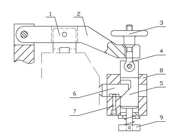
[0011] like figure 1 It shows that the invention provides a thrust clamping device, including the fixture body, a sleeve 8 fixed on the fixture body, as a squeeze knob 3 as the force application device.Cross -block 6, right clamp 6 tail end is a wedge -shaped surface, which drives the swinging arm 2 of the clip 1 clamping workpiece, and the tail of the swing arm 2 hinges on the fixture body.U -shaped end, drive the sliding shaft 5 of the right clip 6 clamping workpiece, and a wedge -shaped hole in the middle of the sliding shaft 5.There is a shaft shoulder 9 that can prevent the sliding shaft 5 from away from the sleeve 8, and the upper end and the rotating rod 4 hinged.There is a formal groove. The sleeve 8 is set in a limited position 7. The limit sales 7 inserted into the strip slot in the middle of the right clip 6, thereby limiting the sliding position of the right clamp 6.
[0012] The specific method is: When the two -way clamping device wants to implement the clamping func...
PUM
 Abstract
Description
Claims
Application Information