Knife lip wiping apparatus

A knife lip and air knife technology, which is applied in the field of knife lip wiping devices and devices for cleaning foreign matter attached to the knife lip of air knives. It can solve the problems of easy wear of the knife head, inability to adjust the blowing angle, and jamming, etc., and achieve improved cleaning. effect of effect

Active Publication Date: 2014-11-26
SHANGHAI MEISHAN IRON & STEEL CO LTD
View PDF5 Cites 0 Cited by
  • Summary
  • Abstract
  • Description
  • Claims
  • Application Information

AI Technical Summary

Problems solved by technology

[0005] 1. In order to ensure the uniformity of the airflow ejected from the strip-shaped lip of the air knife, and then to facilitate the control of the uniformity of the coating, the gap between the air knife lips is a symmetrical arc with a small gap in the middle and gradually increasing gaps on both sides (see figure 2 ), and what CN101768711A adopts is that the blade is placed on the surface of the upper lip, and the head of the blade is inserted into the lip at the same time, and the whole blade and the cutter head move left and right along the lip under the action of the cylinder to realize scraping, so that the cutter head It will make a linear displacement, resulting in that the slag attached to the left and right sides of the knife lip and the surface of the lower lip cannot be effectively removed
[0006] 2. In actual use, the blowing angle of the lip of the air knife needs to be adjusted according to the different technological requirements of the production line (that is, the device needs to rotate at a certain angle, generally within ±10°), and the head of the cleaning blade in CN101768711A is inserted into the lip In the mouth, the rotation of the air knife device will be restricted, so that the spray angle cannot be adjusted
[0007] 3. The head of the cleaning blade in CN101768711A is inserted into the lip. The gap between the lip of a normal air knife is generally between 0.5-2.0mm. The thickness of the blade inserted into the lip should be <0.5mm, and the blade that is too thin is easy to be attached to the lip. The slag is stuck, the cutter head is not only easy to wear, but also affected by the high-pressure airflow from the lip, the cleaning effect is not ideal

Method used


Image

  • Knife lip wiping apparatus
  • Knife lip wiping apparatus
  • Knife lip wiping apparatus

Examples


Embodiment Construction

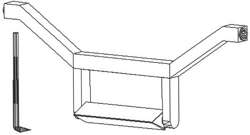
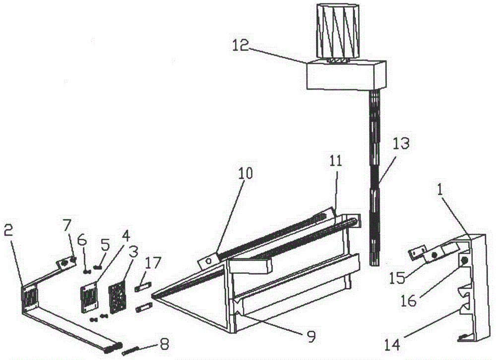
[0021] The basic structure of the air knife lip wiping device of the present embodiment is as follows: image 3 As shown, the air knife device has a blowing lip with a triangular cross-section. The back side of the air knife device away from the lip has a horizontal rail 9 extending along the length direction, and a rotatable horizontal screw 11 driven by a reduction motor 12 on the air knife device through a universal connecting shaft 13 and a helical gear. The air knife device is equipped with a triangular wiping frame composed of a fixed " Figure 4 As shown, four hexagon socket bolts 5 pass through the upper and lower pressure plates 17 respectively to line the rectangular wiping body 3 with the mesh liner 4, pass through the spring 6 respectively, and screw on the front bracket 2, that is, the rectangular wiping body liner is Behind the mesh liner, it is installed on the front bracket by springs. Therefore, after assembly, the wiping body can be pressed against the lip by...


PUM


Abstract

The invention relates to a knife lip wiping apparatus, and belongs to the technical field of metallurgical surface treatment. The apparatus comprises an air knife device having a blowing lip and a triangular cross section, a wiping frame which forms a moving pair with the air knife device and can move along the length direction of the air knife device is arranged on the air knife device, and the position of the wiping frame adjacent to the lip of the knife is provided with a wiper which is positioned adjacent to the lip under an elasticity action. The knife lip wiping apparatus has the following beneficial effects: the wiper will overcome the influences of the high-pressure airflow ejected from the lip under the elastic action when the wiping apparatus works, so the full and effective contact with the air knife lip is realized, and the flexible wiper can cover the external surface of the lip; and the knife lip wiping apparatus can protrude into the gap of the lip by means of deformation, and wipes the lip in the translation process, so the cleaning effect of the lip is substantially improved.

Description

technical field [0001] The invention relates to a device for cleaning foreign matter attached to the lip of an air knife, in particular to a device for wiping the lip of an air knife, and belongs to the technical field of metallurgical surface treatment. Background technique [0002] The air knife is the key process equipment on the hot-dip galvanizing and hot-dip galvanizing production lines in the modern steel industry. Usually the air knife is installed on the top of the zinc pot. After the steel strip leaves the zinc pot, it passes through two pieces of air knife devices continuously. Each device has a strip-shaped lip that exceeds and traverses the entire width of the strip, and uniform high-pressure air is sprayed from the lip. Scrape off the excess zinc and aluminum-zinc solution on the surface of the strip before solidification, so as to achieve the purpose of controlling the coating of the strip. In the actual production process, the high-pressure airflow ejected f...

Claims


Application Information

Patent Timeline
Patent Type & Authority Patents(China)
IPC IPC(8): C23C2/16
Inventor 陈绍林
Owner SHANGHAI MEISHAN IRON & STEEL CO LTD
Why Eureka
Try Eureka