A control method, device and system for a dust removal fan
A technology of dust removal fan and control method, which is applied in the direction of pump control, mechanical equipment, machine/engine, etc., can solve the problems of increasing pipeline system loss and not obvious energy saving effect, and achieve the effect of saving electric energy and good energy saving effect
- Summary
- Abstract
- Description
- Claims
- Application Information
AI Technical Summary
Problems solved by technology
Method used
Image

Examples
Embodiment 1
[0077] see Figure 4 As shown, this embodiment discloses a control method of a dust removal fan, the method comprising:
[0078] S401. Obtain the current material quantity. The amount of material referred to in this embodiment is the flow of material on the trolley of the sintering system. Specifically, the material quantity can be read from the computer of the sintering system. It should be pointed out that the change of material volume is mainly affected by two factors, one big and one small: the big factor is the change of output, when the production capacity needs to be increased in a certain month or a certain day, it is necessary to increase the material volume (can be used in the sintering system This will also lead to a large change in the amount of dust, and then the air volume required for dust removal needs to be changed accordingly. This is also the main scene to be dealt with in the present invention. After that, the amount of material will remain relatively sta...
Embodiment 2
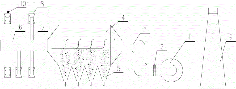
[0091] The method is further described below in combination with specific scenarios based on the above embodiment. In this embodiment, there are n dust raising points (or posts), and the dust removal fan motor is driven by a frequency conversion system, which is specifically controlled by a frequency conversion controller. figure 1 middle 10 position) respectively set the density meter Y 1 ···Y n , each density meter can be set within 2m radius of the corresponding dust point, and these density meters are used to monitor the dust particle density ρ of each dust point in real time 1 ···ρ n . According to the assumption in the previous embodiment, the ρ 1 ···ρ n are regarded as the same or approximately the same, so ρ is used in the following r to replace ρ 1 ···ρ n any value in . Each density meter and frequency conversion controller are connected with the control computer of the dust removal system, and the control computer of the dust removal system is further connec...
Embodiment 3
[0106] see Figure 7 As shown, this embodiment discloses a control device for a dust removal fan, and the device includes:
[0107] A material quantity acquisition unit 701, configured to acquire the current material quantity;
[0108] The material quantity judging unit 702 is used to judge whether the current material quantity is greater than or less than the preset material quantity, if it is greater, the frequency increase unit is triggered, and if it is less, the frequency decrease unit is triggered;
[0109] The frequency increasing unit 703 is used to gradually increase the frequency from the preset motor frequency of the dust removal fan, and at the same time obtain the dust particle density of the dust raising point until the absolute value of the difference between the dust particle density of the dust raising point and the preset dust particle density Less than or equal to the allowable error;
[0110] The frequency reduction unit 704 is used to gradually reduce th...
PUM
 Abstract
Description
Claims
Application Information
 - R&D
- Intellectual Property
- Life Sciences
- Materials
- Tech Scout
- Unparalleled Data Quality
- Higher Quality Content
- 60% Fewer Hallucinations
Browse by: Latest US Patents, China's latest patents, Technical Efficacy Thesaurus, Application Domain, Technology Topic, Popular Technical Reports.
© 2025 PatSnap. All rights reserved.Legal|Privacy policy|Modern Slavery Act Transparency Statement|Sitemap|About US| Contact US: help@patsnap.com