

Imaging apparatus and imaging method
The technology of an imaging device and imaging method, which is applied in image communication, television, color television, etc., can solve the problems of difficult synchronous control and accurate control of convergence angle, etc.
- Summary
- Abstract
- Description
- Claims
- Application Information
AI Technical Summary
Problems solved by technology
Method used
Image

Examples
no. 1 example
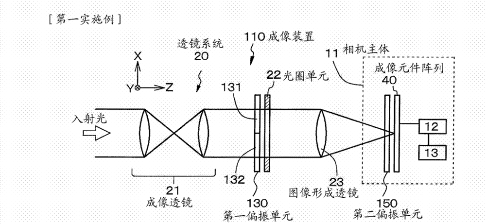
[0067] The first embodiment relates to an imaging device and an imaging method according to the first aspect of the present disclosure, and more particularly, to an imaging device and an imaging method that images a subject as a stereoscopic image.
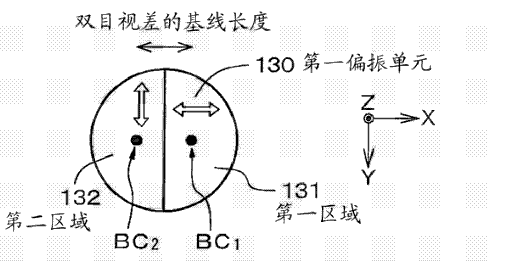
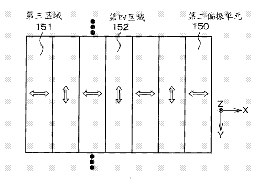
[0068] exist Figure 1A A conceptual diagram of the imaging device according to the first embodiment is illustrated in , in Figure 1B with 1C Schematic diagrams illustrating the polarization states of the first polarization unit and the second polarization unit are respectively illustrated in Figure 2A A conceptual diagram of light reaching the imaging element array through the lens system, the first region in the first polarizing unit, and the third region in the second polarizing unit is illustrated in Figure 2B A conceptual diagram of light passing through the second region in the first polarizing unit, the fourth region in the second polarizing unit and reaching the imaging element array is illustrated in , and in Figure ...
no. 2 example
[0097] The second embodiment is a modification of the first embodiment. In the first embodiment, the first area passes the light L 1 The direction of the electric field is parallel to the first direction. Meanwhile, in the second embodiment, the first area passes through the light L 1 The direction of the electric field forms an angle of 45 degrees with the first direction. The polarization states of the first polarizing unit 230 and the second polarizing unit 250 included in the imaging device according to the second embodiment are schematically illustrated in Figure 6A with 6B middle.
[0098] exist Figure 7 A conceptual diagram of an imaging element array 40 having a Bayer arrangement is illustrated in . Even in the second embodiment, in the imaging element array 40, one pixel includes four imaging elements (a red imaging element R for receiving red light, a blue imaging element B for receiving blue light, and two Green imaging element G) for receiving green light....
no. 3 example
[0101] The third embodiment is also a modification of the first embodiment. In the imaging device according to the third embodiment, in the first polarizing unit 330, a central region 333 is provided between the first region 331 and the second region 332, and the central region that has passed through the central region 333 passes through the polarization state of light does not change from the polarization state of the light prior to being incident on the central region 333 . That is, central region 333 is polarization independent.
[0102] Meanwhile, when the incident light passes through the first polarizing unit, the amount of light decreases in proportion to the spectral characteristics and extinction ratio, and its brightness becomes dim. In this case, the extinction ratio is the ratio of the amount of light to be selected and passed by the polarizer to the amount of leaked light not selected by the polarizer and to be reflected or absorbed. Specifically, in the case o...
PUM
 Abstract
Description
Claims
Application Information