
Panel radio telescope

A radio telescope and flat panel technology, applied in the field of communication, can solve the problems of high cost and difficult processing of radio telescopes, and achieve the effect of easy manufacturing and processing and low cost

Active Publication Date: 2013-04-10
KUANG CHI INST OF ADVANCED TECH +1
View PDF3 Cites 0 Cited by
  • Summary
  • Abstract
  • Description
  • Claims
  • Application Information

AI Technical Summary

Problems solved by technology

[0004] The technical problem to be solved by the present invention is to provide a flat-panel radio telescope with simple processing and low manufacturing cost in view of the defects of difficult processing and high cost of existing radio telescopes

Method used


Image

  • Panel radio telescope
  • Panel radio telescope
  • Panel radio telescope

Examples


Embodiment Construction

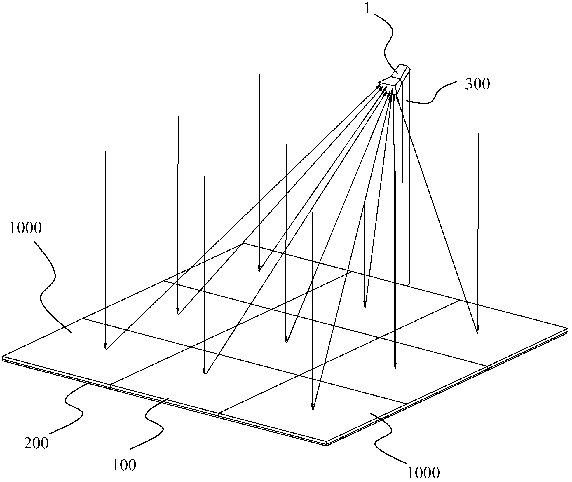
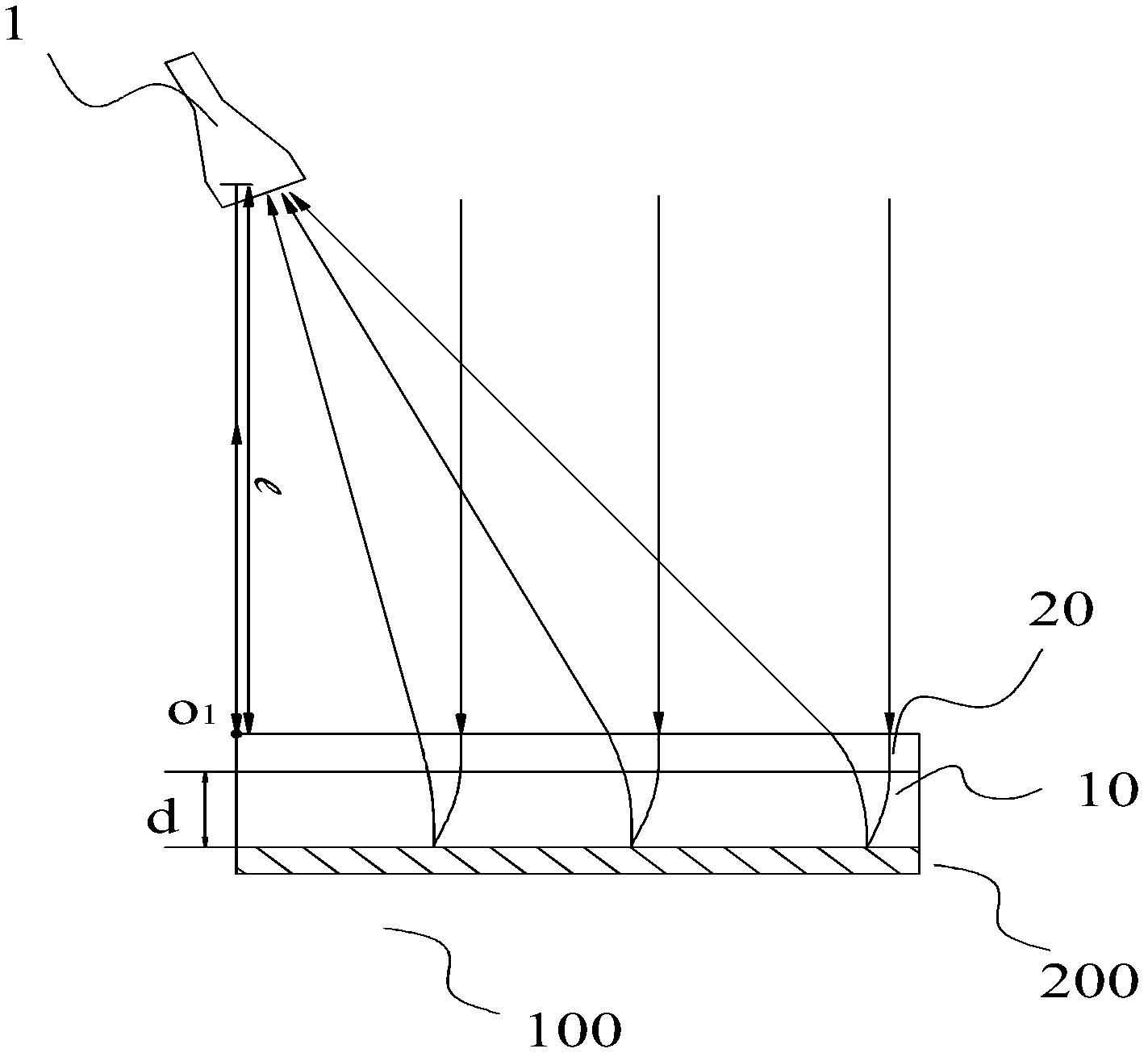
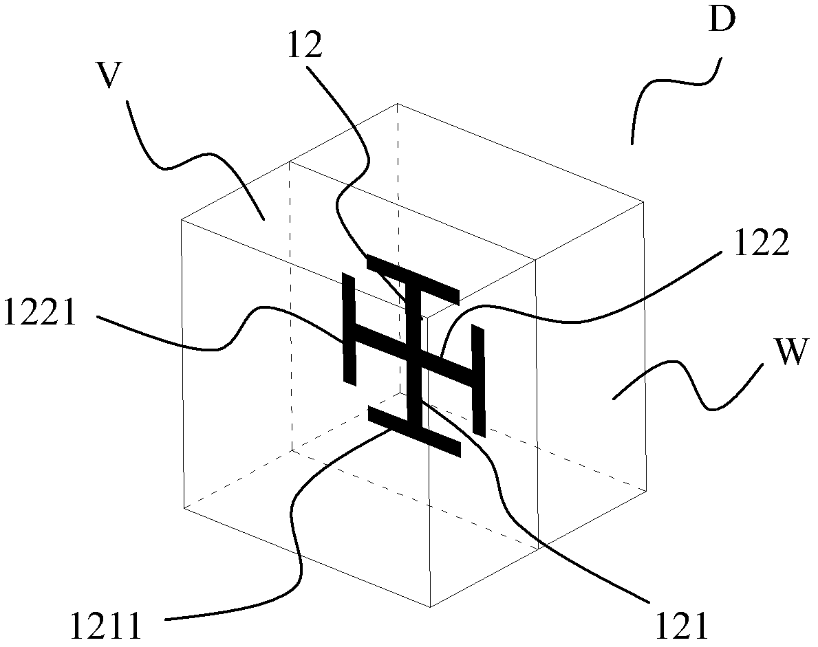
[0037] Such as Figure 1 to Figure 5 As shown, the flat panel radio telescope according to the present invention includes a metamaterial flat panel antenna 100 arranged behind the receiver 1. The metamaterial flat panel antenna 100 includes a core layer 10 and a reflector 200 arranged on one side surface of the core layer. The core layer 10 includes at least one core layer sheet 11, which includes a sheet-like substrate 13 and a plurality of artificial microstructures 12 arranged on the substrate 13, with a certain point as the center of the circle, the core layer The refractive index at the same radius on the slab is the same, and the refractive index gradually decreases with the increase of the radius. The line connecting the center of the circle and the receiver 1 is perpendicular to the core layer 11, and the center of the circle is different from the core layer 11 The center coincides with each other, that is, the receiver is not on the central axis of the core layer, and ...


PUM


Abstract

The invention discloses a panel radio telescope. The panel radio telescope comprises metamaterial panel antenna which is arranged on the back portion of a receiver. The metamaterial panel antenna comprises a core layer and a baffle-board which is arranged on a lateral surface of the core layer and the core layer comprises at least one core layer slice layer. The core layer slice layer comprises base material which is in a slice shape and a plurality of artificial microstructures which are arranged on the base material. A fixed point is regarded as a center of a circle, the refractive indexes are the same at places which are located on the core layer slicer layer with the same radiuses and gradually decrease as the increasing of the radiuses. A ligature of the center of the circle and the receiver is vertical to the core layer slice layer, and the center of the circle does not coincide with a center of the core layer slice layer. Due to the fact that the slice-shaped metamaterial panel antenna replaces a traditional parabolic antenna, the panel radio telescope is easy to manufacture and process and low in cost.

Description

Technical field [0001] The present invention relates to the field of communication, and more specifically, to a flat panel radio telescope. Background technique [0002] Radio telescope (radio telescope) refers to the basic equipment for observing and studying radio waves from celestial bodies. It can measure the intensity, frequency spectrum and polarization of radio waves from celestial bodies. A radio telescope mainly includes two parts, namely an antenna and a receiving system. The antenna is used to collect radio waves. The receiving system usually includes a high-sensitivity receiver that amplifies radio signals, information recording equipment, signal processing equipment, and display equipment. The basic principle of a traditional radio telescope is similar to that of an optical reflecting telescope. The projected electromagnetic wave is reflected by a precise mirror and reaches the common focus in phase. Using a rotating parabola as a mirror is easy to achieve in-phase ...

Claims


Application Information

Patent Timeline
IPC IPC(8): H01Q15/00H01Q15/23H01Q19/06H01Q19/10
Inventor 刘若鹏季春霖岳玉涛
Owner KUANG CHI INST OF ADVANCED TECH
Learn More