Multifunctional manipulator claw
A technology of multifunctional machinery and manipulator claws, which is applied in the direction of manipulators, chucks, manufacturing tools, etc., can solve problems such as the increase of multiple objects, the inability to clamp the claws at the same time, and the clamping force of the claws. Productivity, increased friction, enhanced adaptability effects
- Summary
- Abstract
- Description
- Claims
- Application Information
AI Technical Summary
Problems solved by technology
Method used
Image

Examples
Embodiment 1
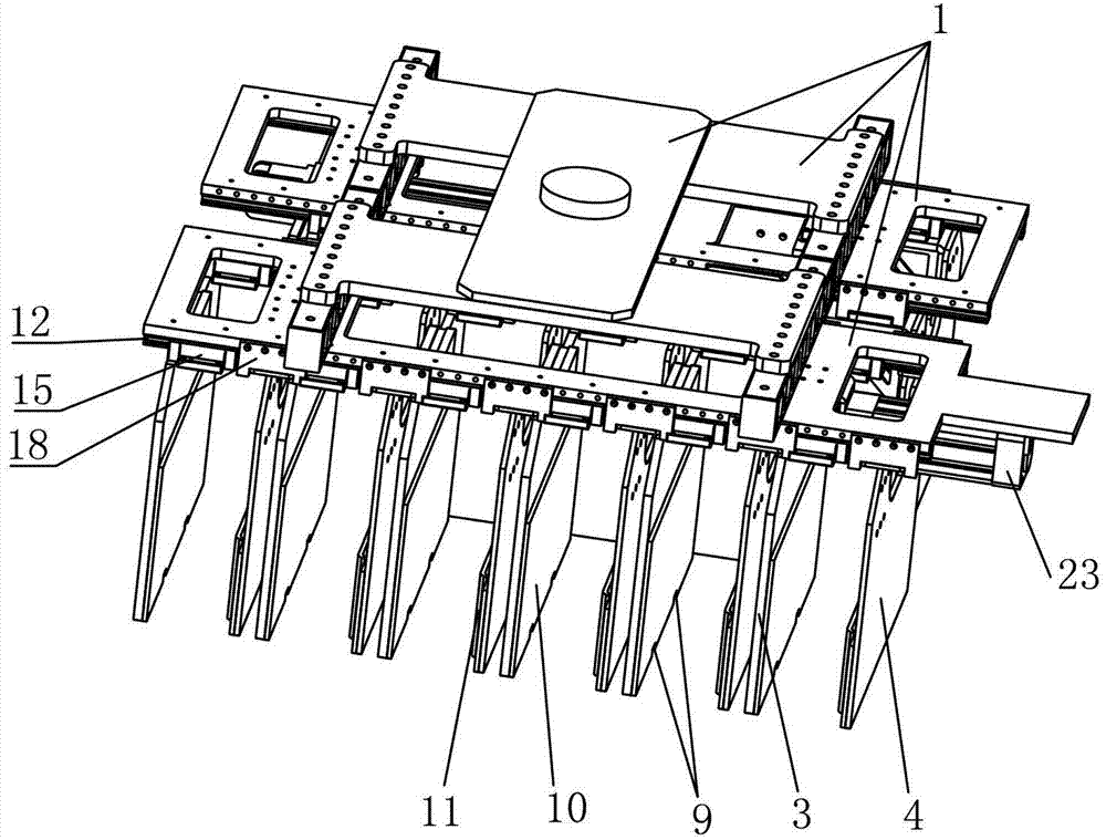
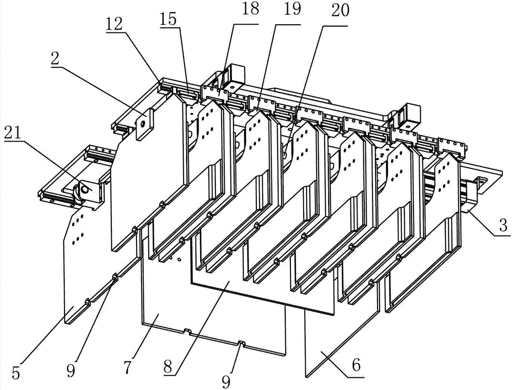
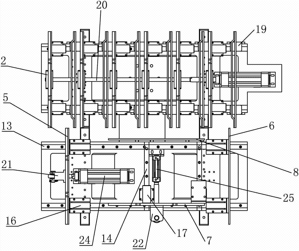
[0030] Such as figure 1 and figure 2 As shown, the multifunctional manipulator claw installed on the robot in this embodiment includes: a skeleton 1, a first joint 2, a left grab claw 3, a right grab claw 4, a left sorting claw 5, a right sorting claw 6, a front claw 7. Rear claw 8, laser sensor 9, friction plate 10, elastic element 11, first pair of guide rails 12, second pair of guide rails 13, third pair of guide rails 14, first slider 15, second slider 16, third pair of guide rails Slider 17, limit plate 18, limit block 19, transmission rod 20, second joint 21, third joint 22, first hydraulic cylinder 23, second hydraulic cylinder 24, third hydraulic cylinder 25.
[0031] The skeleton 1 of the multifunctional manipulator claw is provided with six left grab claws 3 and right grab claws 4 in parallel, wherein the six left grab claws 3 are connected with corresponding first sliders 15, and the first slider 15 is installed on On the first pair of guide rails 12 and can slid...
Embodiment 2
[0038] See Figures 4 to 6 , the multifunctional mechanical gripper provided by this embodiment, with respect to the modification of embodiment 1 is:
[0039] Such as Figure 4 , Figure 5 As shown, a fourth sliding block 31 is provided between the six right claws 4 and the first pair of guide rails 12 , so that the six right claws can slide freely on the first pair of guide rails 12 . A first hydraulic cylinder 23 is arranged on the skeleton 1, and six right grasp claws 4 are connected with the fourth hydraulic cylinder 32 through a second transmission rod 34 and a fourth joint 33, and the second transmission rod 34 passes through the six left grasping claws. Get the through hole 35 of claw 3, when the fourth hydraulic cylinder 32 works, six right grab claws 4 can move relative to the left grab claw 3, and its motion mode is controlled by robot computer. This improvement can increase the maximum distance between the left grabbing claw 3 and the right grabbing claw 4 to ada...
Embodiment 3
[0042] The modification of this embodiment is: replace the first hydraulic cylinder 23, the second hydraulic cylinder 24, the third hydraulic cylinder 25, the fourth hydraulic cylinder 32, the fifth hydraulic cylinder 36 and the sixth hydraulic cylinder with six independent cylinders. The hydraulic cylinder 39 is provided with a small air pump and a high-pressure gas storage tank on the skeleton 1, and uses air pressure as the power source of the manipulator claw, so that the control speed is faster, the pipeline arrangement is convenient, and it is convenient to adjust the air pressure of the gas storage tank according to the type of the object and change the manipulator. claw grip.
PUM
 Abstract
Description
Claims
Application Information