
Three-degree-of-freedom movable joint mechanism and bionic robot

A technology of bionic robots and movable joints, which is applied in the field of bionic robots, can solve problems such as the compliance of robots, and achieve the effects of good safety, realism and good compliance

Active Publication Date: 2013-04-17
深圳中智卫安机器人技术有限公司
View PDF7 Cites 7 Cited by
  • Summary
  • Abstract
  • Description
  • Claims
  • Application Information

AI Technical Summary

Problems solved by technology

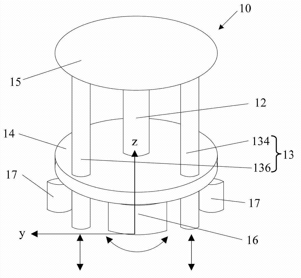
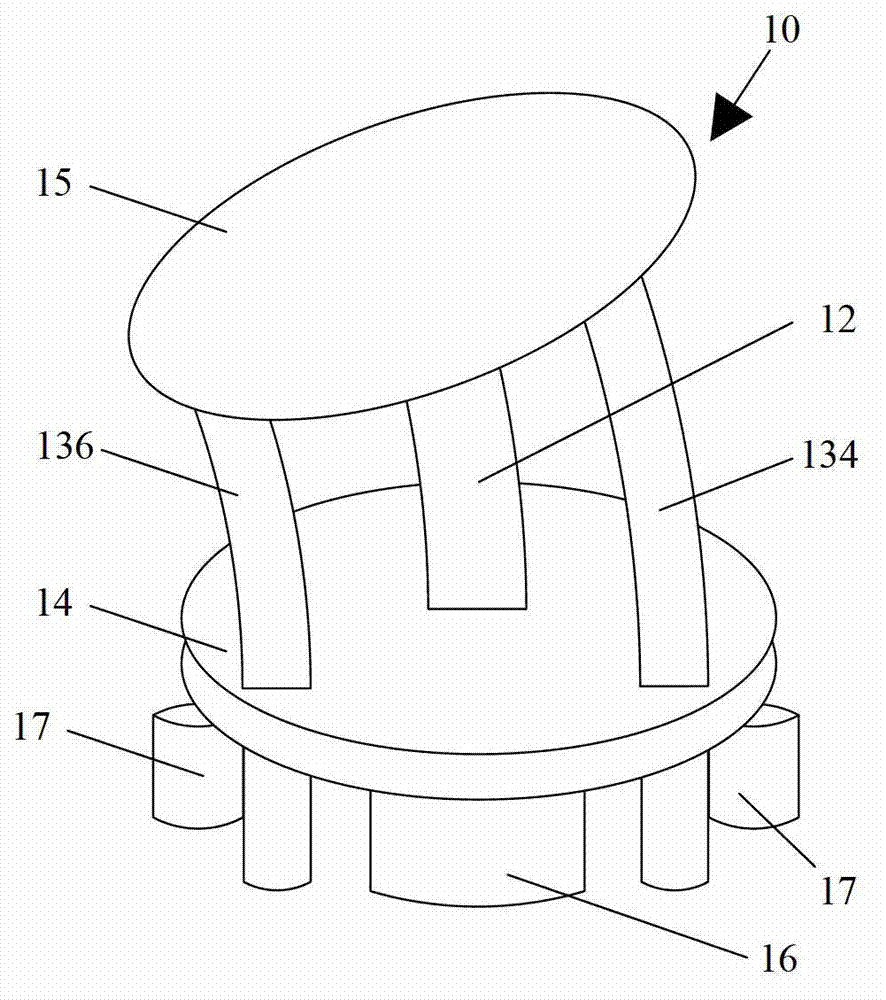
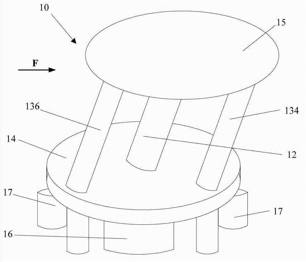
[0003] The purpose of the present invention is to provide a three-degree-of-freedom movable joint mechanism and a bionic robot with the joint mechanism, which aims to solve the compliance problem of the neck movement of the robot in the prior art, and provide tilting, pitching and yaw motions

Method used


Image

  • Three-degree-of-freedom movable joint mechanism and bionic robot
  • Three-degree-of-freedom movable joint mechanism and bionic robot
  • Three-degree-of-freedom movable joint mechanism and bionic robot

Examples


no. 1 example

[0039] Please also refer to Figure 7 with Figure 8 , the joint mechanism 10 includes a rotating wheel 18 connected between the second driver 17 and the first support member 134 , the rotating wheel 18 is axially connected with the second driver 17 and cooperates with the first support member 134 . When the second driver 17 is activated, it drives the rotating wheel 18 to rotate and provides the upward or downward thrust of the first support member 134, thereby adjusting the length of the first support member 134 between the first connecting member 14 and the second connecting member 15 , that is, the first supporting member 134 moves a certain distance between the first connecting member 14 and the second connecting member 15 . The thrust may be generated in a frictional manner.

no. 2 example

[0041] Please refer to Figure 9 , the joint mechanism 10 includes a gear 19 connected between the second driver 17 and the first support member 134 , and the gear 19 is axially connected with the second driver 17 . Each of the first support members 134 has a matching portion 1340 that cooperates with the gear 19 (the second support member 136 has a matching portion 1360 ), and the matching portion 1340 is disposed along the length direction of the first support member 134 . The matching parts 1340, 1360 can be any shape that fits with the gear 19, for example, when the gear 19 is a spur gear, the matching parts 1340, 1360 are designed as a straight tooth shape meshed with the gear 19; When it is a helical gear, the matching parts 1340 and 1360 are designed as a helical tooth shape meshed with the gear 19; but it is not limited to the enumerated shapes. When the second driver 17 is activated, the gear 19 is driven to rotate, and the gear 19 and the matching portion 1340 are e...


PUM


Abstract

The invention is applicable to the field of robots and provides a three-degree-of-freedom movable joint mechanism which solves the problem of compliance in movement of the neck of a robot in the prior art and provides tilting, pitching and swaying actions. The three-degree-of-freedom movable joint mechanism is used for a bionic robot to simulate human neck movement and comprises a master supporting part used for simulating the cervical vertebra, an auxiliary supporting part used for simulating cervical muscle, a first drive for driving a head part to move and a second drive which is matched with the auxiliary supporting part to drive the head part to move, and the master supporting part and the auxiliary supporting part are connected with the head part and a body part respectively and made of elastic materials. The invention further provides a bionic robot with the joint mechanism. The supporting parts made of elastic materials form the continuous joint mechanism to achieve fine compliance, and the first drive is used for providing swaying actions and the second drive is used for providing tilting and pitching actions to provide high safety and sense of reality.

Description

technical field [0001] The invention belongs to the field of robots, in particular to a three-degree-of-freedom movable joint mechanism and a bionic robot with the joint mechanism. Background technique [0002] The study of bionic robots that simulate human motion is an important topic in the field of robotics, and has attracted the attention and interest of many researchers and scholars. In the structural design of bionic robots, the rational design of each joint of the robot is very important, especially the compliance of the joint mechanism. For example, the robot that imitates the neck movement can be realized through different mechanical structures, and the common one is to realize the rotation movement through a single spherical joint. There is a gap between the movement effect of this kind of structure and the actual joint composition of the human neck. The compliance of the neck movement makes it difficult to provide realistic movement effects. Contents of the inv...

Claims


Application Information

Patent Timeline
IPC IPC(8): B25J17/02B25J9/00
Inventor 林天麟阎镜予钟翔宇
Owner 深圳中智卫安机器人技术有限公司
Learn More