

Injection molding machine
A technology of injection molding machine and cooling mechanism, applied in the field of injection molding machine, can solve problems such as poor responsiveness of electromagnets, and achieve the effect of improving responsiveness
- Summary
- Abstract
- Description
- Claims
- Application Information
AI Technical Summary
Problems solved by technology
Method used
Image

Examples
Embodiment Construction
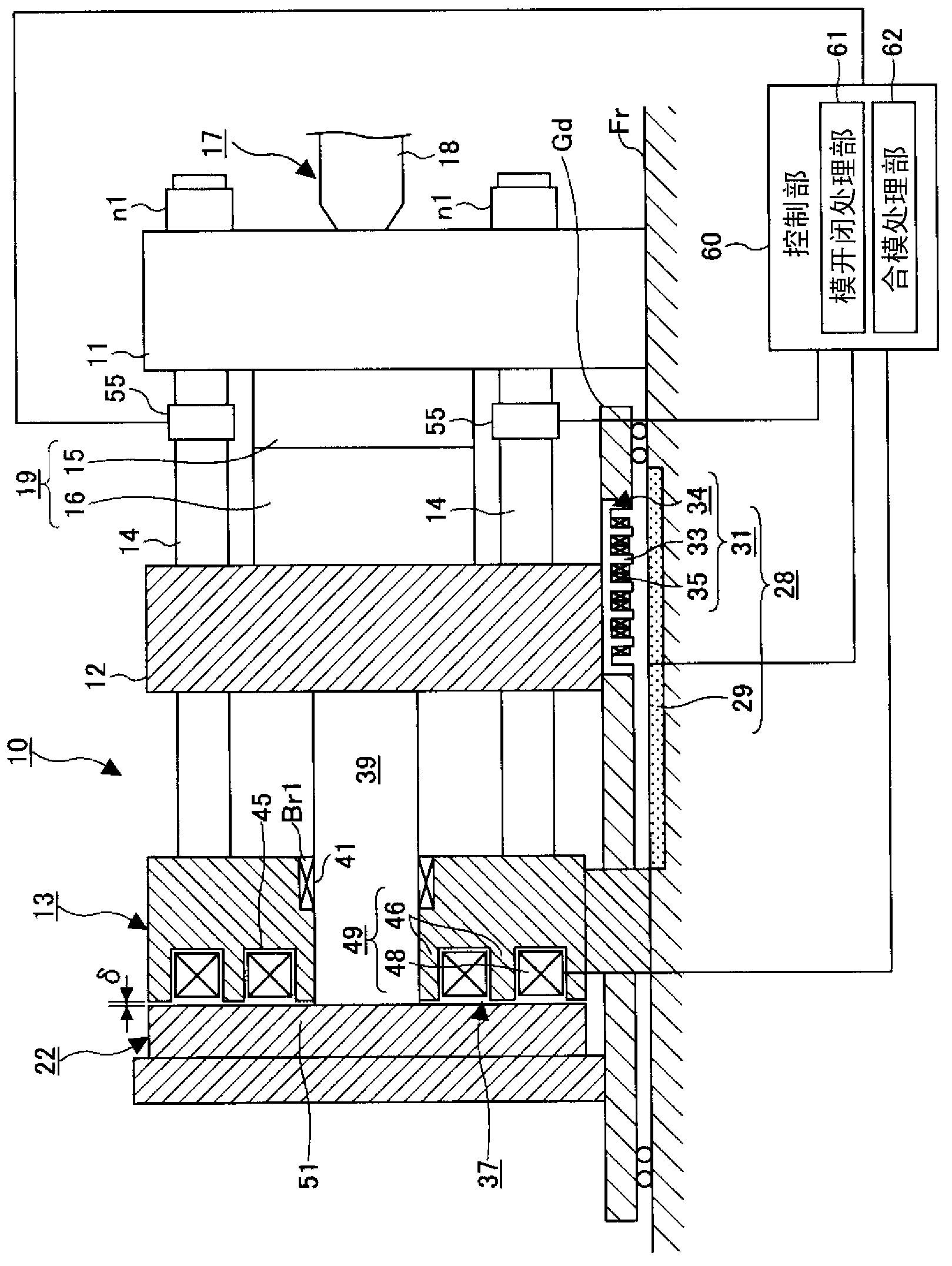
[0026] Hereinafter, the best mode for carrying out the present invention will be described with reference to the drawings. In this embodiment, the mold clamping device assumes the moving direction of the movable platen at the time of mold closing as the front, and the direction of movement of the movable platen at the time of mold opening as the rear, and the injection device as follows: The movement direction of the screw during injection is assumed to be forward, and the direction of movement of the screw during metering is assumed to be backward.
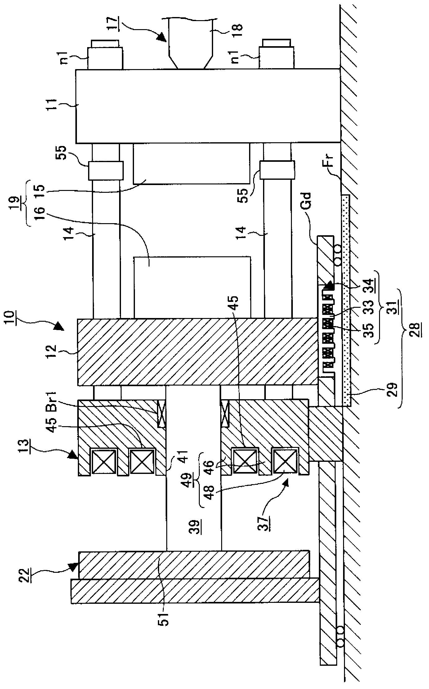
[0027] figure 1 It is a figure showing the state when the clamping device in the injection molding machine according to the embodiment of the present invention closes the mold, figure 2 It is a figure which shows the state at the time of mold opening of the clamping device in the injection molding machine concerning embodiment of this invention. In addition, in figure 1 and figure 2 In , the hatched parts represent the main...
PUM
 Abstract
Description
Claims
Application Information