Fiber substrate, and interior material using this
A fiber base material and interior material technology, applied in the direction of thin material processing, non-woven fabrics, layered products, etc., can solve the problems of fiber base material weight reduction, fiber base material rigidity reduction, and difficulty in ensuring rigidity, etc., to achieve Excellent appearance, ensuring handling rigidity, and excellent handling rigidity effect
- Summary
- Abstract
- Description
- Claims
- Application Information
AI Technical Summary
Problems solved by technology
Method used
Image
Examples
no. 1 Embodiment approach )
[0038] The fibrous base material 1 of the first embodiment will be described with reference to the drawings.
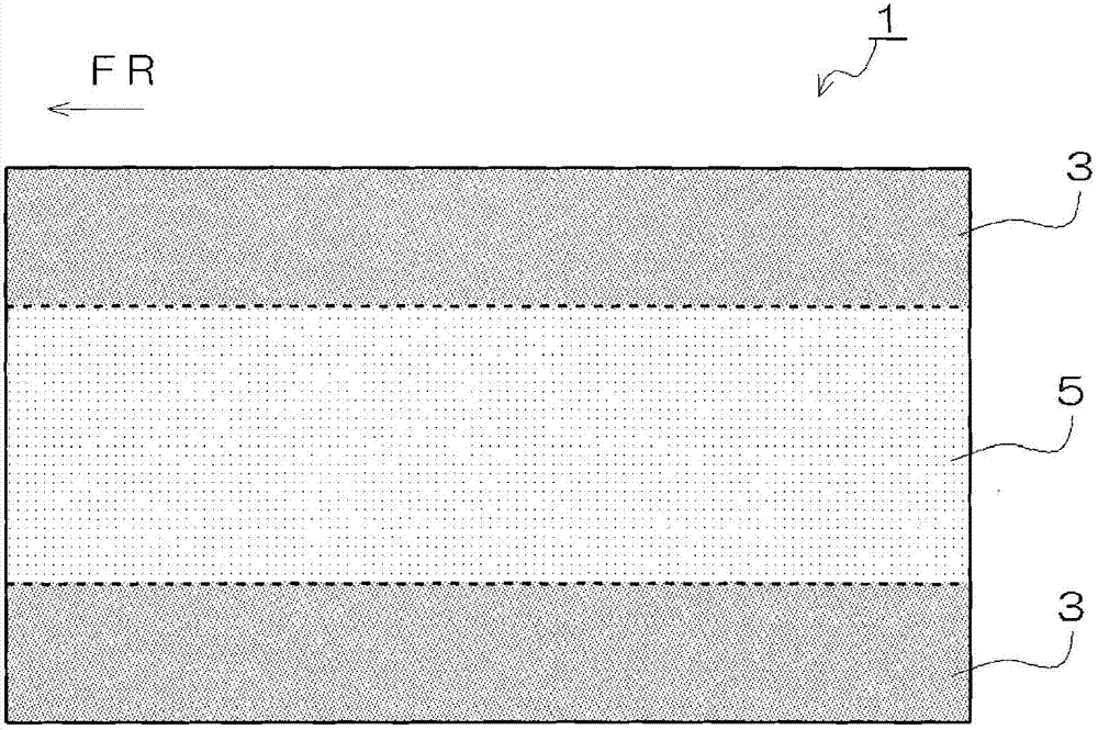
[0039] The fibrous base material 1 is a plate-shaped fibrous base material in which fibers are bonded with a thermoplastic resin. Furthermore, the fibrous base material 1 is characterized by having a plurality of regions having different basis weights.
[0040] Such as figure 1 As shown, the fibrous base material 1 of the present embodiment has a first region 3 having a larger basis weight and a second region 5 having a smaller basis weight than the first region 3 . in addition, figure 1 Different shades of shading in represent different weights per unit area. The darker the shade, the greater the weight per unit area ( Figure 3 ~ Figure 5 also the same). also, figure 1 Arrow FR in the arrow indicates the front side when the fibrous base material 1 is used for an automobile interior material.
[0041] The fibrous base material 1 of the present embodiment is...
no. 2 Embodiment approach )
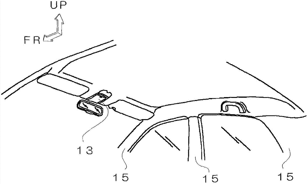
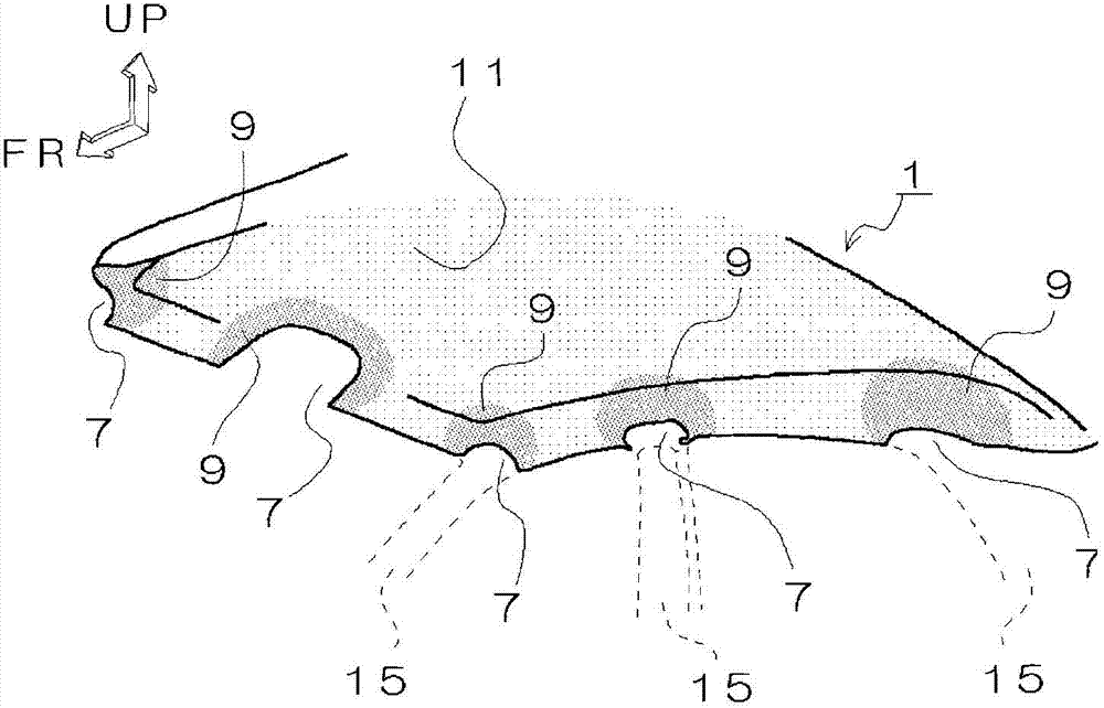
[0066] refer to figure 2 and image 3 The fibrous base material 1 of the second embodiment will be described. figure 2 of car interiors can have image 3 Fiber substrate 1. In addition, the same reference numerals are assigned to the same parts as those of the first embodiment described above, and descriptions of structures, functions, and effects are omitted. And, with figure 1 Similarly, the difference in shade shades indicates the difference in weight per unit area. Darker shades indicate greater weight per unit area. also, figure 2 and image 3 The arrow FR shows the front side of the car, and the arrow UP shows the upper ( Figure 4 also the same).
[0067] The fibrous base material 1 has a notch 7, and the basis weight of the peripheral region 9 of the notch 7 is larger than the basis weight of the outer region 11 outside the peripheral region. A notch 7 is formed in the fiber base material 1, and when the fiber base material 1 is installed as a roof materi...
no. 3 Embodiment approach )
[0070] refer to Figure 4 The fibrous base material 1 of the third embodiment will be described. figure 2 of car interiors can have Figure 4 Fiber substrate 1. In addition, the same code|symbol is attached|subjected to the same part as said 2nd Embodiment, and description of a structure, operation|movement, and an effect is abbreviate|omitted.
[0071] and figure 1 The fiber base material 1 shown is the same, and the fiber base material 1 that can be used as the roof material of an automobile is configured with belt-shaped, larger areas per unit area at both edge portions, thereby making the rigidity of the fiber base material 1 both sides Becomes high. In addition, each notch 7 corresponding to a portion where each strut 15 is disposed is formed in the region where the basis weight is large. That is, each notch 7 corresponding to each strut 15 is arranged such that the notch 7 is included in a region with a large basis weight. Furthermore, the weight per unit area of...
PUM
| Property | Measurement | Unit |
|---|---|---|
| thickness | aaaaa | aaaaa |
Abstract
Description
Claims
Application Information
 - R&D
- Intellectual Property
- Life Sciences
- Materials
- Tech Scout
- Unparalleled Data Quality
- Higher Quality Content
- 60% Fewer Hallucinations
Browse by: Latest US Patents, China's latest patents, Technical Efficacy Thesaurus, Application Domain, Technology Topic, Popular Technical Reports.
© 2025 PatSnap. All rights reserved.Legal|Privacy policy|Modern Slavery Act Transparency Statement|Sitemap|About US| Contact US: help@patsnap.com


