Stacking system and stacking method for steel plate

A steel plate and stacking technology, applied in the steel plate stacking system and the field of stacking, can solve the problems of inability to meet the requirements of precise positioning of steel plate stacking, complicated equipment maintenance, and large system investment, so as to reduce potential safety hazards and surface scratches on steel plates. damage, improved stability and safety, and low investment costs

Active Publication Date: 2013-04-17
LAIWU IRON & STEEL GRP
View PDF9 Cites 6 Cited by
  • Summary
  • Abstract
  • Description
  • Claims
  • Application Information

AI Technical Summary

Problems solved by technology

When the invention is applied to the stacking of wide and thick plates, a large number of sensors and related equipment need to be installed in multiple locations on site, resulting in large investment and cumbersome equipment maintenance.
[0004] Chinese patent CN201121095Y discloses a new crane locator for cranes, which is designed for the low accuracy and high cost of the existing radio frequency card and radio frequency cable positioning methods
When this invention is used for steel plate stacking, due to its own design reasons, it can only achieve linear and precise positioning, and cannot meet the requirements of steel plate stacking for plane precise positioning

Method used


Image

  • Stacking system and stacking method for steel plate
  • Stacking system and stacking method for steel plate
  • Stacking system and stacking method for steel plate

Examples


Embodiment 1

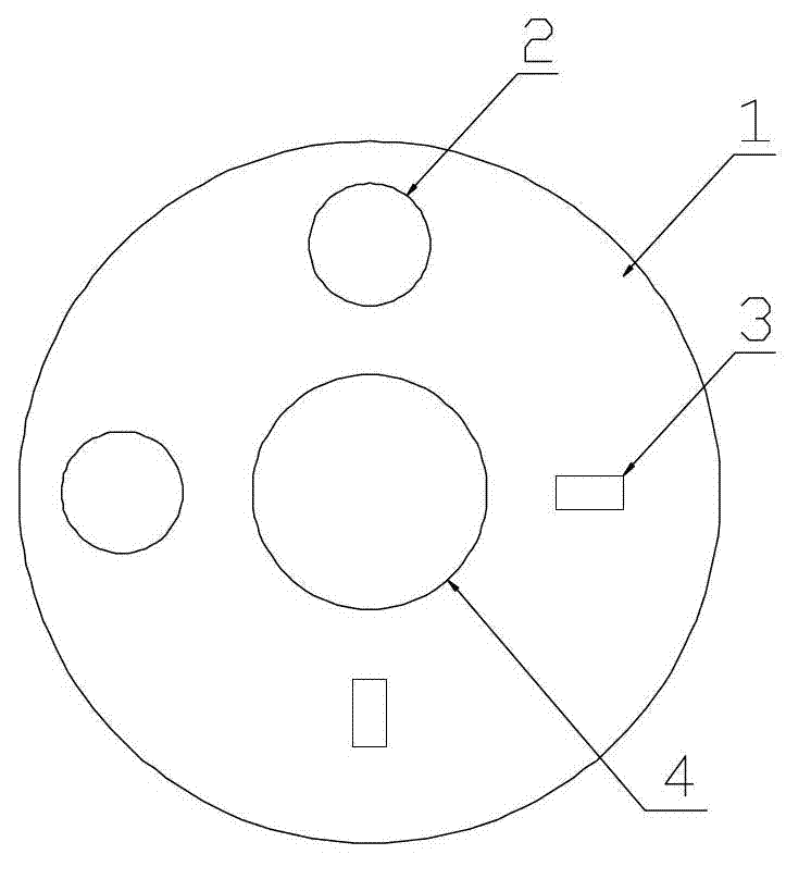
[0046]A steel plate stacking system, including a lighting subsystem 2 , an aiming and sighting subsystem 3 , a camera subsystem 4 , a display subsystem 5 , a position indication point 15 and a telescopic rod 10 .

[0047] Such as figure 1 As shown, the lighting subsystem 2 composed of two high-beam lighting lamps distributed at right angles, the camera subsystem 4 and the viewing and aiming indicator subsystem 3 composed of two red laser lights distributed at right angles are arranged in the integrated base 1. The indicator lines projected by the two red laser lights intersect perpendicularly to form a cross-shaped target aiming baseline.

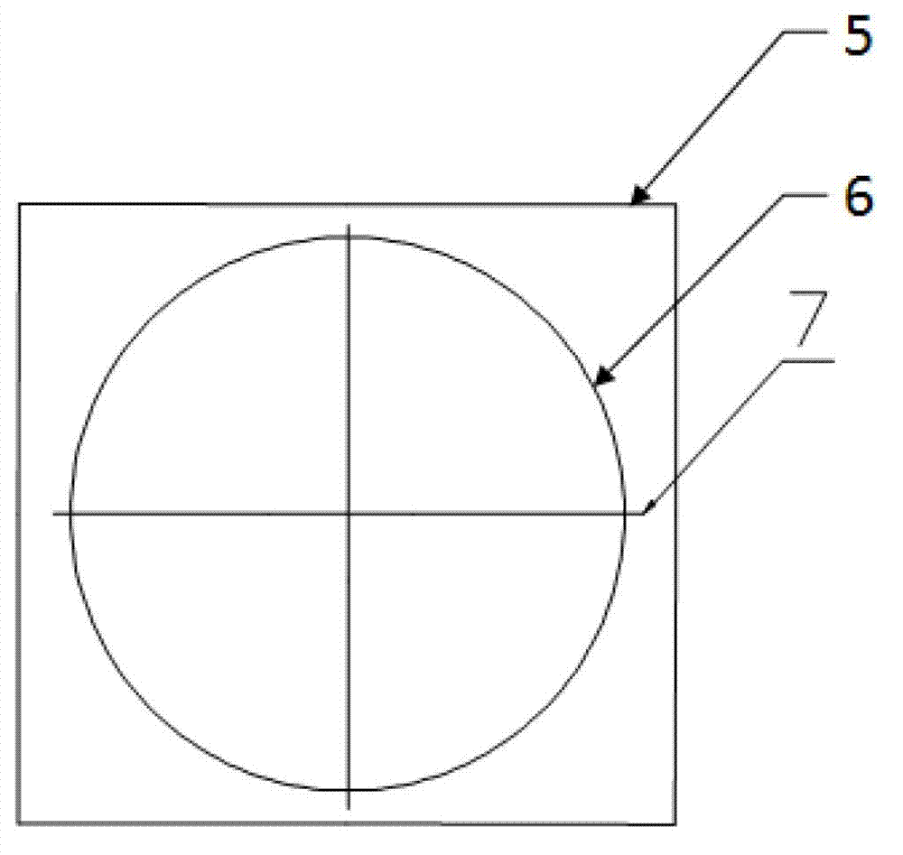
[0048] Such as figure 2 As shown, the display subsystem 5 displays the picture taken by the camera subsystem 4, and a field of view marking circle 6 is integrated on the display subsystem 5, and the cross-shaped target aiming baseline passes through the camera subsystem 4 The center of the field of view marking circle 6 imaged on the dis...


PUM


Abstract

The invention relates to a stacking system and a stacking method for a steel plate. The stacking system comprises illumination subsystems, view indication subsystems, camera subsystems, a display subsystem, a position indicating point and a telescopic link, wherein integrated base bodies are arranged on a second section of telescopic tube and a first section of telescopic tube of the telescopic link respectively; and each integrated base body is provided with the illumination subsystems, the view indication subsystems and the camera subsystem. The stacking method comprises the steps: 1) the distance between the camera subsystem on the second section of telescopic tube of the telescopic link and a cross beam middle line of an electromagnetic lifter is half of the width of the lifted steel plate; 2) positions of a travelling crane and a lifting tool of the electromagnetic lifter are observed and adjusted through a cruciform goal aiming baseline, corner parts of the steel plate are superposed with a right angle of the cruciform goal aiming baseline; and 3) the steel plate is lifted and moved to above a target stacking zone, a right angle of the position indicating point is superposed with the right angle of the cruciform goal aiming baseline, and the steel plate is laid down. With the adoption of the system, planar accurate positioning of the steel plate during the stacking course can be realized, and the stacking efficiency and stacking quality are improved.

Description

technical field [0001] The invention relates to the technical field of iron and steel, in particular, the invention relates to a steel plate stacking system and a stacking method. Background technique [0002] In the existing production process of wide and thick plates, the produced steel plates need to be stacked and transferred multiple times for reasonable heat treatment, storage and transportation. Stacking steel plates is an important task. Since the stacking uniformity and stacking efficiency have a great impact on stacking safety and subsequent production, the stacking process requires the close cooperation of ground commanders and skilled operators to complete successfully. , In this process, the stacking efficiency is low and the labor load is large, which limits the organization and production of the wide and thick plate production line or heat treatment workshop. At present, there are many new technologies for precise positioning in the lifting system, but these ...

Claims


Application Information

Patent Timeline
Patent Type & Authority Applications(China)
IPC IPC(8): B66C13/46B66C13/16B65G57/04
Inventor 张冠锋李文钱王博刘洪银马琳杨州刘美吴昌飞刘斌刘艳芹
Owner LAIWU IRON & STEEL GRP
Why Eureka
Try Eureka