Steel rib and steel frame beam connecting node

A technology for connecting nodes and steel bar connectors, which is applied in the directions of buildings and building structures, can solve the problems of affecting the smoothness of the concrete surface, low engineering construction efficiency, and hindering the travel of the sliding form, and achieves high construction efficiency, simple design and implementation, and structural stable effect

Inactive Publication Date: 2013-04-17
CENT RES INST OF BUILDING & CONSTR CO LTD MCC GRP +1
View PDF5 Cites 3 Cited by
  • Summary
  • Abstract
  • Description
  • Claims
  • Application Information

AI Technical Summary

Problems solved by technology

The corbels are exposed outside the concrete, which affects the smooth surface of the concrete and hinders the stroke of the s

Method used


Image

  • Steel rib and steel frame beam connecting node
  • Steel rib and steel frame beam connecting node
  • Steel rib and steel frame beam connecting node

Examples


Embodiment 1

[0040] The connection node between the steel frame and the steel frame beam in this embodiment includes a steel frame located in the concrete and a steel frame beam located outside the concrete, and the connection node between the steel frame and the steel frame beam also includes a set on the steel frame 1. An end plate whose front is exposed outside the concrete and does not protrude from the concrete; the steel frame beam is connected to the front of the end plate.

[0041] The steel frame is divided into a steel frame column and a steel frame beam. An end plate is provided at the joint between the steel frame beam or the steel frame column and the steel frame beam, and the front of the end plate is placed on the concrete when pouring concrete. and the end plate is flush with or slightly below the concrete so that the steel frame beam is no longer attached to an embed fully anchored in the concrete or to a corbel protruding in the concrete It has the characteristics of conv...

Embodiment 2

[0043] In this embodiment, on the basis of any of the above-mentioned embodiments, in the connection node between the steel frame and the steel frame beam in this embodiment, the steel frame is provided with reinforcing ribs or reinforcing ribs at the connection with the steel frame beam . The steel frames include Wang-shaped steel frames, cross-shaped steel frames, and H-shaped steel frames.

[0044] Such as Figure 4-Figure 5 As shown, the steel column 12 is provided with a reinforcement rib 20 at the joint with the corbel 15;

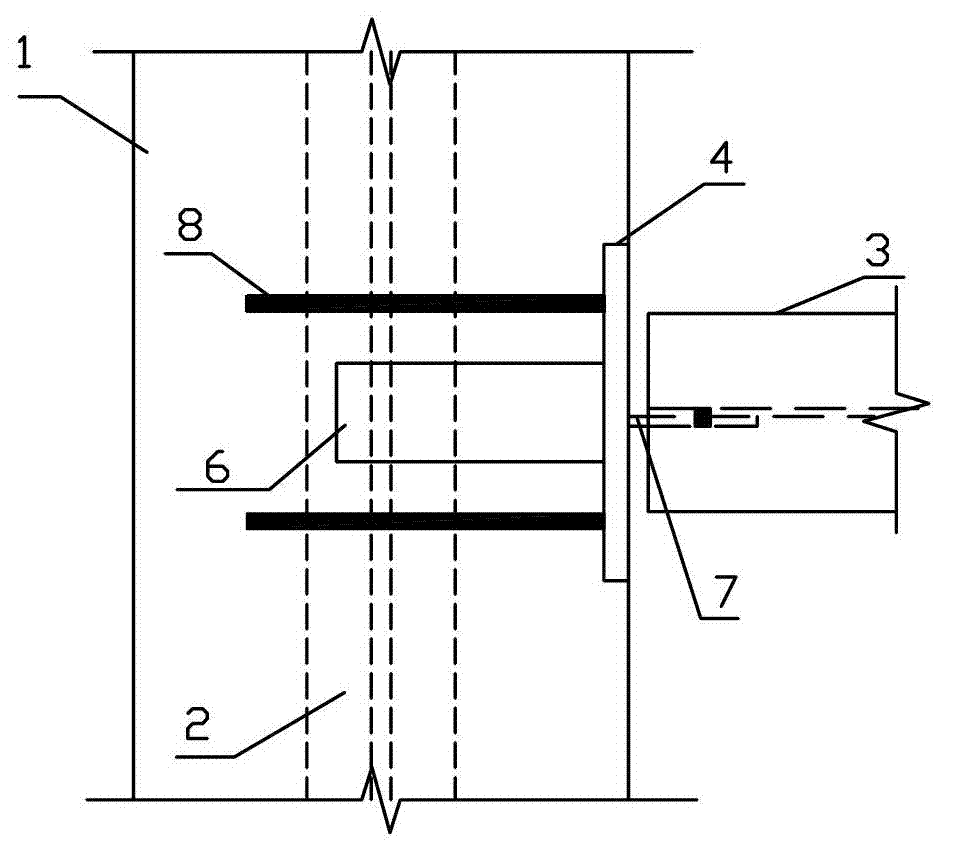
[0045] Such as Figure 7-Figure 8 As shown, the steel column 120 is provided with a reinforcement rib 200 at the joint with the corbel 150;

[0046] Such as Figure 12 As shown, the king-shaped steel frame is provided with a reinforcing rib 202 at the joint with the steel frame beam;

[0047] Such as Figure 13 As shown, the cross-shaped steel frame is provided with a reinforcing rib 203 at the connection with the steel frame beam;

[0048] Su...

Embodiment 3

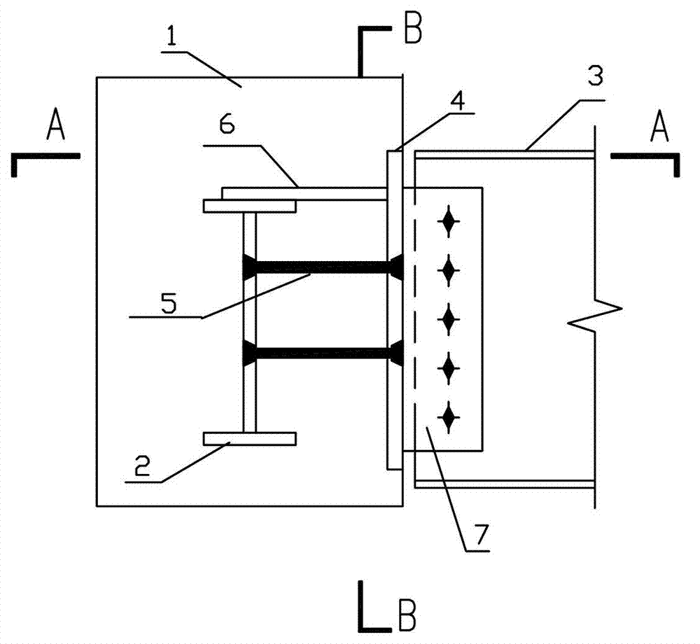
[0051] Such as Figure 1-Figure 3 As shown, the connection node between the steel frame and the steel frame beam in this embodiment includes the steel frame beam 2 and the steel frame beam 3 located in the concrete, and the connection node between the steel frame and the steel frame beam also includes a An end plate 4 flush with the outer surface of the concrete 1; the steel frame beam 3 is connected to the front of the end plate 4.

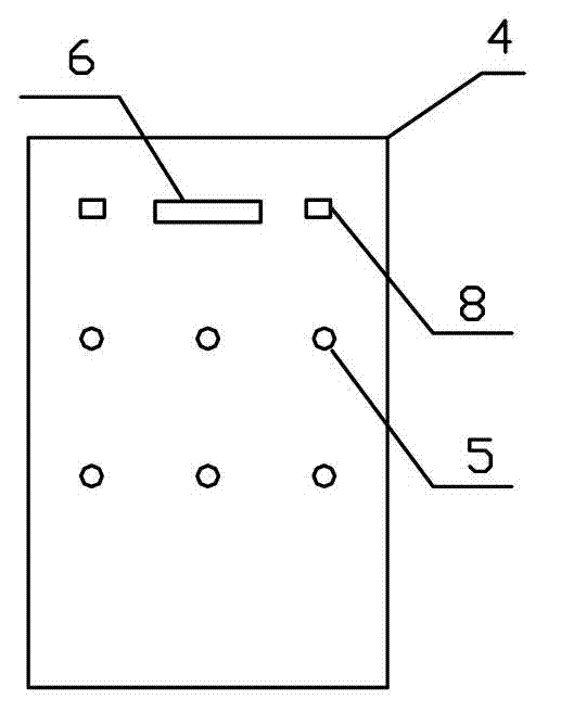
[0052] The steel frame beam 2 is arranged horizontally, and several steel bars 5 are arranged between the steel frame beam 3; Wherein, the symbol 9 in the end plate 4 is the plug welding hole for the welding of the steel bar 5 .

[0053] In this embodiment, one end of the end plate 4 used to connect the steel frame beam 2 and the steel frame beam 3 is connected to the steel frame beam 2 before pouring the concrete 1 to form a whole, and when the concrete 1 is poured, the end plate 4 The front of the concrete 1 is flush with the outer surface of...


PUM


Abstract

The invention discloses a steel rib and steel frame beam connecting node, which is designed for solving the problems of being instable in structure caused by mutual interference of corresponding buried pieces of steel rib and steel frame beam, difficult to design, low in construction efficiency caused by projected connecting bracket and the like in the existing connecting process of steel rib and steel frame beam. The steel rib and steel frame beam connecting node disclosed by the invention comprises a steel rib positioned in concrete, a steel frame beam outside the concrete, and an end board arranged on the steel rib and exposed out of the concrete and not projected out of the concrete on the front face; and the steel frame beam is connected with the front face of the end board. The interference between the steel rib and the steel frame beam is eliminated, so that the steel rib and steel frame beam connecting node has the advantages of being stable in structure, convenient to transport, and convenient to pass through in order by reinforcing steel bars in the concrete; and the front face of the end board is not projected out of the concrete, so that the steel rib and steel frame beam connecting node is simple for connection, convenient for concrete slip-form construction and low in engineering cost.

Description

technical field [0001] The invention relates to the field of construction, in particular to a connection node between a steel frame and a steel frame beam. Background technique [0002] Most of the current high-rise buildings adopt the steel-concrete composite structure of reinforced concrete core tube and steel frame beam; among them, the connection nodes between the steel frame beam and the concrete member in the steel frame have the following two types: [0003] The first method: preset embedded parts in the concrete, and connect the steel frame beam with the embedded parts after the concrete is formed. [0004] The second type: a steel corbel is set on the steel frame of the concrete member, the corbel part is exposed to concrete, and the corbel is connected by a steel frame beam. [0005] In the specific implementation process, the first connection node has the following deficiencies: [0006] The embedded part is separated from the steel frame, and the anchor bar usu...

Claims


Application Information

Patent Timeline
IPC IPC(8): E04B1/58
Inventor 卞晓芳吴昌栋刘鹏郭晓杨春峰陈水荣桂宇飞李相杰王频李伟男
Owner CENT RES INST OF BUILDING & CONSTR CO LTD MCC GRP
Why Eureka
Try Eureka